300 u 6 volt gen to 12 volt alternator condition question

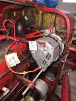
I recently posted about how best to mount the new alternator for this conversion. I've completed the installation. Following the instructions I've been using the next step was to attach the A wire to the Bat terminal which I did. It was then I realized that the instructions I'm using appear to be for a 3 wire alternator.
I purchased this alternator over a year ago then changed my mind about doing the conversion. I saved several discussions on the topic but now can no longer find the correct instructions. When I search I usually find debates on the pros and cons of converting or parts of discussions from folks well into the process. Worst case is the dreaded diagram.
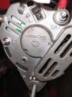
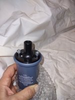
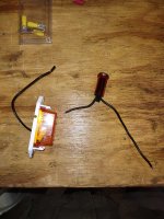
This is a Hitachi alternator with an internal voltage regulator. I also purchased a 12 volt coil that does not require an external resistor. I've attached pictures below. I'd appreciate if anyone can provide simple instructions on how to proceed from here. I also switched the wires on my Anmeter but perhaps that doesn't matter at this point. Thanks for the help! Paul
 

Attachments

  • IMG_20231229_153158268.jpg
    IMG_20231229_153158268.jpg
    2.1 MB · Views: 24
  • IMG_20231229_153350126.jpg
    IMG_20231229_153350126.jpg
    3.2 MB · Views: 21
  • IMG_20231229_153458167.jpg
    IMG_20231229_153458167.jpg
    2.9 MB · Views: 20
  • IMG_20231229_155453675.jpg
    IMG_20231229_155453675.jpg
    995 KB · Views: 20
Previous YT post with info
So you connected the wire from the “A” or armature terminal on the generator to the output terminal of the alternator. That will work but you have to make a change at the voltage regulator. At the regulator, disconnect the wire from the GEN terminal and connect it to the BAT terminal so there are now two wires connected there. That is verbiage from number 8 in the YT post I am linking in the reply by mkirsch. I personally would bolt the two wires together and tape them. The voltage regulator can then be removed so there is no worry of an odd short occurring in it. With a one wire you will also disregard 7, 14 & 15. You should be set if you follow that. I hope your alternator actually works as a 1 wire, if not connections will need to be made to the “S & L” spade terminals on the back of the alternator. Sorry the link wants to drop in at the beginning of the discussion, used to it dropping where I have the cursor.
 
The terminals on a Hitachi are labeled Bat (big output terminal), L and S (two 1/4inch spade terminals). The Bat terminal attaches as you have intended using 10 gauge wire(I like to have a fuse or fuse link in that wire rated above the alternator output amps by 10% to prevent fires and smoke. )The battery end of that wire on a 300U should attach to the ammeter load terminal so the ammeter reads charge/discharge as intended.
The L terminal should be attached with 12gauge wire to a diode or trailer marker light bulb, or a 10ohm 10 watt resistor, (if diode, the band mark should be toward the alternator and be a 4 amp with 150PIV) One source to show diode. The source end of the diode should connect to the positive side of the ignition coil. This supplies exciting current to the alternator. The S terminal is connected directly to the Bat terminal with 12gauge wire (about 6 inches with a loop terminal) this senses output voltage to keep the alternator at 14.2 or so volts. Jim
Jim. Since I have an Hitachi alternator I'm going to follow up based on your reply. I've run the new 10 gauge wire to Anmeter and installed the fuse link. Beginning with your 2nd paragraph I have two questions. The first is will either of the lights pictured below work. The orange only has one wire and the red circular with 2 wires is an LED. This is what my local auto parts store is carrying. Second question, can you please explain what a terminal loop or better yet what I need to do to make one. Thanks as always. Paul
 

Attachments

  • IMG_20231230_144122145.jpg
    IMG_20231230_144122145.jpg
    2.6 MB · Views: 6
I may not be the most knowledgeable to make this reply. The single wire lamp will not work unless you mount it so the ground is isolated and you can connect a wire to allow a series connection through the lamp. There is a possibility that the LED could work if it can carry enough current to energize the the excite circuit of the alternator voltage regulator. The LED will have to be wired where current can flow to the alternator but not flow back towards the ignition. Here is a generic wiring diagram of what you should essentially have in the end. The fine print at the bottom has some additional information.
Edit to add: Your fusible link should go in the wire at the starter that runs up to the ammeter, refer to the diagram. That way it will protect the entire wiring system of the tractor.
Generic alternator install diagram
 
Last edited:
Jim. Since I have an Hitachi alternator I'm going to follow up based on your reply. I've run the new 10 gauge wire to Anmeter and installed the fuse link. Beginning with your 2nd paragraph I have two questions. The first is will either of the lights pictured below work. The orange only has one wire and the red circular with 2 wires is an LED. This is what my local auto parts store is carrying. Second question, can you please explain what a terminal loop or better yet what I need to do to make one. Thanks as always. Paul
The situation is that the marker lamp needs to be in series with the excite wire, and not to a ground. This is as Used Red MN indicates. The 2 lead LED is unlikely to work unless a 10 ohm 10 watt resistor is wired in parallel with it. If you use it for a dash light in a hole, that would be nice. The resistor passes enough current to cause initial excitation. The resistor alone will work. When the alternator begins to charge, the L terminal becomes 14.? volts positive and will keep the tractor running with the key off unless the lamp diode or resistor is in the circuit. A diode from a defunct alternator bridge will work as well. A auto electric shop will have them by the score. Jim
 
I may not be the most knowledgeable to make this reply. The single wire lamp will not work unless you mount it so the ground is isolated and you can connect a wire to allow a series connection through the lamp. There is a possibility that the LED could work if it can carry enough current to energize the the excite circuit of the alternator voltage regulator. The LED will have to be wired where current can flow to the alternator but not flow back towards the ignition. Here is a generic wiring diagram of what you should essentially have in the end. The fine print at the bottom has some additional information.
Edit to add: Your fusible link should go in the wire at the starter that runs up to the ammeter, refer to the diagram. That way it will protect the entire wiring system of the tractor.
Generic alternator install diagram
Used Red MN. Thank you for this reply and your previous reply. I think I figured out how to use the one wire indicator light. I simply attached wire to the metal grommet at the other end of the light which I believe was designed to be screwed to a metal service as a ground. When I touch both wire ends to my 12v battery, the light operates. I read that the LED doesn't create the same amount of resistance as a standard bulb. I'm studying your diagram and fusible link statement. Right now I have the fusible link installed come off the A wire and running to the positive pole of the Anmeter. Is that sufficient to protect the wiring system. I'm going to respond to Jim Nicholson with same question when I get the chance. Thanks again. Paul
 
The situation is that the marker lamp needs to be in series with the excite wire, and not to a ground. This is as Used Red MN indicates. The 2 lead LED is unlikely to work unless a 10 ohm 10 watt resistor is wired in parallel with it. If you use it for a dash light in a hole, that would be nice. The resistor passes enough current to cause initial excitation. The resistor alone will work. When the alternator begins to charge, the L terminal becomes 14.? volts positive and will keep the tractor running with the key off unless the lamp diode or resistor is in the circuit. A diode from a defunct alternator bridge will work as well. A auto electric shop will have them by the score. Jim
Thanks Jim. I think I made the one wire standard marker light usable. I simply attached a second wire to what looks like a grommet on the opposite side of the wired side. I think this grommet, which when you flip the unit over is attached to a metal bar that runs back to the light bulb is the second pole of the light. When I connect each wire to the + - of my 12 v battery, the light operates.
Finally, if you read used Red MN reply it discusses the location of the fusible link. Right now it is installed on the new wire running from the A terminal to the positive terminal of the Anmeter. Is this that correct or reasonable placement? Thanks Paul
 

We sell tractor parts! We have the parts you need to repair your tractor - the right parts. Our low prices and years of research make us your best choice when you need parts. Shop Online Today.

Back
Top