control unit for a Strongway gantry crane trolley

ltknutson

New User
About six years ago I purchased a gantry crane, Strongway hoist and Strongway trolley from Northern tool. It has proven to be one of the most useful
tools in my shop. A couple of days ago I was moving the crane from one tractor to another when the control unit for the trolley caught on something on
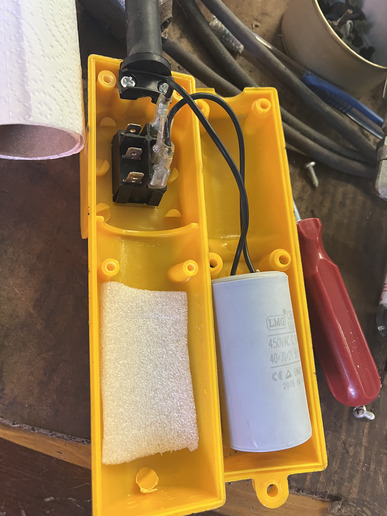
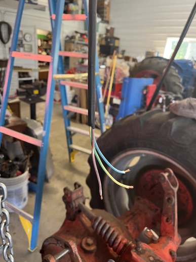
tractor one and pulled the unit right off the cord. I had a control unit on my floor and a cord with three dangling wires. I took the control unit apart to
see if the wires could be easily re-connected. Turns out there is a capacitor or something in the handle. I'm reluctant to just start re-connecting wires
as I'm afraid of burning out the capacitor (or whatever it is). I am diligent about keeping all my user manuals but can't find this one. I called Northern
Tool but they no longer carry this unit and cannot provide me with a user manual. The unit is made in China and I've had no luck finding a user manual
on-line. I'm putting this message up to see if any readers have one of these trolleys, would be willing to take the cover off their control unit, take a
picture showing how the wires are attached (which colors go where) and e-mail it to me. I would be grateful.
cvphoto159767.jpg


cvphoto159768.jpg
 
Looks like the cap is still connected to the 2 outside terminals. Was there a jumper between the 2 center terminals?

All the cap is for is to help reduce arcing inside the switch to lengthen its life.

To determine where the other three go, you need to find the 'common'.

Power it up and carefully start touching the wires together until you find the one that when touched to either wire will make the hoist move. That will go to the center terminal. Just be careful to not connect all 3 together at the same time!

Each of the others will go to the end terminals. If it runs backward, switch the 2 end wires.
 
I think that the controller has power coming into the handle (top of image). if so the common wire (probably brown) might connect to the solder terminal at the black rubber strain relief. If so the other two would go to the end open terminals on the switch. Electricity needs to get into the wires before it can work. If I am wrong about the wires, and they are already powered from the trolley, then you are correct, and the brown is the middle terminal and touching them should work. Jim
 
Capacitor should be connected to the up and down circuit or forward and reverse windings. The two neutrals of the windings are connected together and the white wire of the 115V circuit.

That said, Im surprised that there are only three wires. I would expect at least four.
 

Likely, it's a ''PSC'' (permanent Split Capacitor motor).

One wire would run to the ''HOT'' prong on the power plug, use an Ohmmeter or continuity tester to verify which one. Likely, the brown wire, but check to be sure.

This would run to the center terminal on the switch, do I see a wire connector still there?

The other two wires AND the cap leads go to the outer terminals.

Id you get the colors wrong, UP and DOWN will be reversed and you can swap the leads to correct that.

UqFUaaJ.jpg


Clear as MUD?

Try at your own risk, YAMMV!
 
First of all, thanks to all of you for your comments and suggestions. Now for some clarification: This switch does not control the electric hoist; it controls the trolley that moves the hoist back and forth across the gantry. I was surprised when I opened the switch to find only one empty spade connector. Obviously it was used for one of the wires. I can see NO evidence of how the other two were connected to their respective terminals. The two screws at the top of the unit that may appear to be solder connectors are, in fact, screws that tighten the band that grips the outer wire casing to keep it attached to the switch. Not that it matters, but the wire colors are, respectively, blue, yellow, and purple.
On the switch I'm assuming the center lead is the common, for the power wire, with the other two directing left and right. Once I determine which wire from the unit is the power wire I'm planning to test the switch with a 12V battery just to verify if my assumption on the leads is correct. Then I have two insulated spade connectors to connect the L/R wires. Please jump back in if you think I've missed anything.
 
That makes sense. Two of the wires will do nothing when hooked to the battery (maybe hum) the remaining wire will then be the up/down hot wires. Jim
 
where i used to work, we had 3 10-ton cranes, several times the control wires got caught up on something. we went to a wireless remote control. and never used the wired control again.
 
Well, for any of you who are still following this fiasco, here's the latest. The short story is - it's still not working. I was able to determine, using a multi-meter, which wire was the power wire. It was the yellow/green wire. This was also the wire that had the single quick-disconnect terminal connector, confirmed when I found a fragment of the wire insulation still in the crimp.
I tested the switch using a 6V battery and confirmed that the center terminal would be the feed terminal and the outer two terminals should send the trolley left or right. Also you will note that there were two banks of terminals on the switch. They were not interconnected, side to side.
Attaching quick-disconnects to each wire, I attached them to the terminals opposite of where the capacitor was connected, plugged in the power and - NOTHING. I've tried every combination of wire attachment to the switch with the same result - NOTHING.
So that's where I am tonight. So I'm thinking: A. Could the capacitor have been damaged when the control handle broke free and hit my concrete floor? I don't know enough about capacitors to know if they are enough of a factor to cause this situation. B. Could the wires have touched enough when they stripped free to short out something in the motor? A fuse, perhaps? Although I can see no signs of an electrical short on any of the wires.
 
This is not the control for the hoist itself but for the trolley that moves the hoist back and forth on the gantry.
 
the wires need to be connected into the spades used for the cap and they need to be on the same side of the switch as the power wire
 
AhHa, That's why I only found one spade connector when I opened it up. The other wires had simply been pushed under the spade connectors of the
capacitor. Will try that tomorrow morning and post result.
 
What voltage does the motor use? The capacitor may play a roll in starting the motor in either direction. If you know the power is coming into the switch and it is current thinking that the other two wires are then connected (one or the other through the switch) how does the power get back to the source from the motor. There must be a complete circuit. Jim
 
Success! My thanks, again, to all who responded to my request for feedback and assistance on my issue, particularly to sammydwm who spelled it out clearly. wore out may have been saying the same thing and I just didn't understand it. That's on me. My academic background is financial analysis, not electronics. I've learned tractor restoration as a hobby through reading, doing it, and talking to smart guys like all of you.

No need for any more input on this as my issue has been resolved.
 

We sell tractor parts! We have the parts you need to repair your tractor - the right parts. Our low prices and years of research make us your best choice when you need parts. Shop Online Today.

Back
Top