9n all new wiring assistance

here's what I have
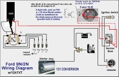
First thing I see is the jumper wire should be same gauge as power from battery and the alternator wire as it will see the full charging current.

That has nothing to do with why it won't start. Guessing you have a pertronix unit in there as the distributor cover does not have a hump for a condenser. Black wire from pertronix unit should go to negative terminal on coil. power from ignition switch should go to positive terminal on coil as well as red wire from pertronix unit. If that is how you have it wired it should work.

If it is wired as I have described and no spark then troubleshooting begins:)
 
I am new to the 9n world. Purchased a 1942 9n, converted to 12v prior to me.
I am getting ready to install the Pertronix Electronic ignition (1247XT) and looking to also renew all of the wiring in the process. I have found wiring info but just have a couple of questions for anyone willing to help out.
1. Pertronix says that I do not need a inline resistor, that the system needs the full 12v. Does this mean that I should also get rid of the Resistor block that looks like a wood square with a coiled wire and 3 screws (which my tractor does not have)? I understand to remove the two tab resistor.
2. the alternator that I have has the obvious power post and also has a two prong plug with one of the wires looped to the post on the alternator and the other goes somewhere I don't recall and I am currently at work.

Do I need to continue to use the alternator 2 prong plug or am i fine just attaching to the post?
GET THE ESSENTIAL MANUALS & CORRECT WIRING DOCUMENTS FIRST -READ THEM. The 9N/2N wiring is different than the 8N. You don't need EI - why? What was 'wrong' with the 6V system? 12V may not be needed either but your call as always. Many switch out jobs are done wrong anyway. If you must, get the DELCO 10-SI 1-Wire or 3-Wire ALT, the belt tensioner, and all wired all correctly. Your 6V coil will need an external in-line 1.5 OHM ceramic resistor or just change it out to a 12V coil. You MUST USE THE OEM 12250 BALLAST RESISTOR in the circuit.

Tim Daley (MI)
 

Attachments

  • 9N & 2N WIRING - 6V & 12V.jpg
    9N & 2N WIRING - 6V & 12V.jpg
    1.7 MB · Views: 26
  • FORD OEM BALLAST RESISTOR - 9N-12250.jpg
    FORD OEM BALLAST RESISTOR - 9N-12250.jpg
    57.8 KB · Views: 22
  • DELCO 10-SI 3-WIRE ALTERNATOR.jpg
    DELCO 10-SI 3-WIRE ALTERNATOR.jpg
    39.9 KB · Views: 23
  • FORD 9N - 2N ESSENTIAL MANUALS.jpg
    FORD 9N - 2N ESSENTIAL MANUALS.jpg
    1.2 MB · Views: 30
GET THE ESSENTIAL MANUALS & CORRECT WIRING DOCUMENTS FIRST -READ THEM. The 9N/2N wiring is different than the 8N. You don't need EI - why? What was 'wrong' with the 6V system? 12V may not be needed either but your call as always. Many switch out jobs are done wrong anyway. If you must, get the DELCO 10-SI 1-Wire or 3-Wire ALT, the belt tensioner, and all wired all correctly. Your 6V coil will need an external in-line 1.5 OHM ceramic resistor or just change it out to a 12V coil. You MUST USE THE OEM 12250 BALLAST RESISTOR in the circuit.

Tim Daley (MI)
While I fully understand your passion for these tractors and wanting to keep each and every one of them as originally built, you really should read all the posts in a thread before just replying to the first post, which was made almost a week ago. It appears most, if not all, of your concerns/questions were already addressed, with written words or pictures, in the thread. While things may not be to your standards, it is the owner's tractor and the owner's choices for how it is equipped. Telling someone "You MUST USE THE OEM 12250 BALLAST RESISTOR in the circuit" is incorrect information at this point, for the wiring of the Pertronix EI kit he has already installed.
 
so if I remove the resistor block, do I just use something to tie all those wires together? I really want to give this tractor the cleanest wire setup I can...not sure that this thing is wired correctly when I got it.
NO!!! You do not yank the OEM Ballast Resistor off. Why would you do that? Gotta understand the 6V/POS GRN Front Mount Distributor and electrical setup. The OEM 9N-12250 Ballast Resistor is part of the coil circuit and used whether you have a 6V or a 12V system. Period. Get your Manuals out. I already posted all of this.

Tim Daley (MI)
 

Attachments

  • FORD OEM BALLAST RESISTOR - 9N-12250.jpg
    FORD OEM BALLAST RESISTOR - 9N-12250.jpg
    57.8 KB · Views: 14
Okay, so everything is wired up and able to start but I am getting no charge to the battery. The alternator is showing charge out the post. I have it wired for single wire. The wire from the post back to the battery is at least 14ga or possibly 12ga. The ammeter isn't showing much of a charge...only getting to just before the 10 on the gauge.
Any ideas? The picture of the guage was taken while not running.
 

Attachments

  • 17130468189502899651367113985856.jpg
    17130468189502899651367113985856.jpg
    1.1 MB · Views: 11
Okay, so everything is wired up and able to start but I am getting no charge to the battery. The alternator is showing charge out the post. I have it wired for single wire. The wire from the post back to the battery is at least 14ga or possibly 12ga. The ammeter isn't showing much of a charge...only getting to just before the 10 on the gauge.
Any ideas? The picture of the guage was taken while not running.
i use 10 gauge for that wire.
 
Okay, so everything is wired up and able to start but I am getting no charge to the battery. The alternator is showing charge out the post. I have it wired for single wire. The wire from the post back to the battery is at least 14ga or possibly 12ga. The ammeter isn't showing much of a charge...only getting to just before the 10 on the gauge.
Any ideas? The picture of the guage was taken while not running.
Regardless of wire size at this point.

You first say you are getting no charge to the battery, and later you say the ammeter is only getting to just before 10. 10 on the plus or minus side? If wired correctly, 10 on the plus would be a charge and 10 on the minus would be a discharge. To confirm charge or not, what is the voltage at the alternator output post when running and what is the voltage at the battery when running?

Post a picture of the diagram you used for wiring it. What gauge wire do you have between the alternator and ammeter? Is the wire from the ammeter to the battery alone on one post, with all other wires on the other post? If you wired from the alternator to the battery, you bypassed the ammeter, and it won't read charge, only discharge caused by loads going through it.
It is showing 10 positive...but the tractor died from too much load behind it in the box blade. Went to go start and the battery was dead. I'll start it up and test voltage numbers and repost.
Thanks for the assistance.
 

Attachments

  • 9N_2N_12v_conv_1247XT.jpg
    9N_2N_12v_conv_1247XT.jpg
    174.9 KB · Views: 16
It is showing 10 positive...but the tractor died from too much load behind it in the box blade. Went to go start and the battery was dead. I'll start it up and test voltage numbers and repost.
Thanks for the assistance.
Start by checking both ends of the battery cables. Is the ground cable on a chassis point or on sheet metal? That wiring should work ok. You only have the one wire between the alternator and junction block, correct?
 
Start by checking both ends of the battery cables. Is the ground cable on a chassis point or on sheet metal? That wiring should work ok. You only have the one wire between the alternator and junction block, correct?
Yes, just the one wire. Ground to chassis. Should I maybe look to doing the 3 wire setup?
 
Yes, just the one wire. Ground to chassis. Should I maybe look to doing the 3 wire setup?
If you have a one-wire alternator, the other two wires are not used, and the spade terminals are often covered by a "rubber" plug to prevent access to them. If you have a three-wire alternator It needs the two wires on the regulator spade terminals wired correctly. You cannot just wire a three-wire alternator "like a one-wire alternator", with just a wire on the battery post, and make it a one-wire alternator.

In looking back through the entire thread, i see you posted in your first post, "2. the alternator that I have has the obvious power post and also has a two prong plug with one of the wires looped to the post on the alternator and the other goes somewhere I don't recall and I am currently at work." Then later in the thread you posted a picture of an alternator which does not have a cap covering the spade terminals. If that is the same alternator as you first posted about, I believe you have a three-wire alternator and need to wire it as such. Did you buy an actual one-wire alternator at some point after that first post?
 
Do you have any other wires, other than ignition, that supply tractor load, or example, lighting or other accessories? It is important which side of the amp meter these wires are connected. Connected on the alternator side of the Amp meter and you will have a Net amp meter, connected on the battery side of the Amp meter and your meter will only read the alternator output and never show negative amps if you are draining the battery. I only mention this because there is a 12 volt conversion kit out there that has an incorrect wiring diagram.
 
Do you have any other wires, other than ignition, that supply tractor load, or example, lighting or other accessories? It is important which side of the amp meter these wires are connected. Connected on the alternator side of the Amp meter and you will have a Net amp meter, connected on the battery side of the Amp meter and your meter will only read the alternator output and never show negative amps if you are draining the battery. I only mention this because there is a 12 volt conversion kit out there that has an incorrect wiring diagram.
Yes, most of us consider a “ non net” reading ammeter “incorrect”, but they also function just fine and at users request, I have even provided such diagrams. Whatever suits the man/company. I don’t rule.
 
Do you have any other wires, other than ignition, that supply tractor load, or example, lighting or other accessories? It is important which side of the amp meter these wires are connected. Connected on the alternator side of the Amp meter and you will have a Net amp meter, connected on the battery side of the Amp meter and your meter will only read the alternator output and never show negative amps if you are draining the battery. I only mention this because there is a 12 volt conversion kit out there that has an incorrect wiring diagram.
He said he wired using the diagram he posted in reply #31. It shows a net reading ammeter as he took everything, except the battery wire, to the junction block then one wire from there to the ammeter.
 
Understood. Thought where the accessories are wired might help in trouble shooting. I don't quite understand how these threads get posted because they show up differently on my phone versus the computer. Took me a while to realize some "new" posts can be 2 years old!
 
Ammeter is only going to show the amperage flow going back to battery and loads, so if no loads like lights and the battery is charged then it will show very little amperage. Better off with a voltmeter but that's another discussion. I would use a heavy wire for alternator output. If you hook a voltmeter to the battery check the voltage then start the tractor and you'll see right away if the alternator is charging.
 
Thanks everyone for the inputs, I'll test batt voltage and running voltage as well and repost with the numbers.
 

We sell tractor parts! We have the parts you need to repair your tractor - the right parts. Our low prices and years of research make us your best choice when you need parts. Shop Online Today.

Back
Top