Bern
Well-known Member
- Location
- Mount Vernon, WA
So I get my 6000 to the point where I can hop in the seat, put it in gear, and drive it outside to finish painting the rear end. Problem is, when I let the clutch out, nothing happened. I can clearly hear the transmission shifting, and I know for a fact that the driveline coupler is engaged.
I take out the rear axle fill plug and look inside with a flashlight. I can clearly see the pinion coupler spinning as I let the clutch out. I figure the problem HAS to be in the diffy because I've already been through both final drives when I put new axle shaft seals in earlier. I had to tear down the finals down to check and re-adjust the axle bearings, which were quite loose. I also put speedi-sleeves on the axle shafts.
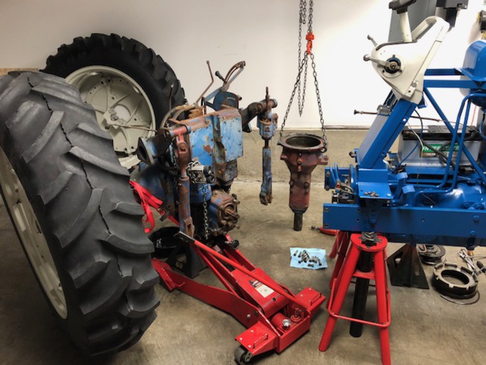
Fortunately, the LH final is the one that has to come off to get at the diffy, and it's conveniently accessible with my overhead hoist. Off comes the rear tire, then the final (oops, nope, gotta split the thing to get the final off to clear the frame rail), then out comes the diffy. Everything looks fine, so I split the diffy in half, figuring the spider gear cross is cracked or some such thing. Everything looks perfect inside the diffy, right down to the "NAA" part numbers on the spider gears! At this point, I think I'm starting to lose my sanity, and that maybe I should change careers or something.
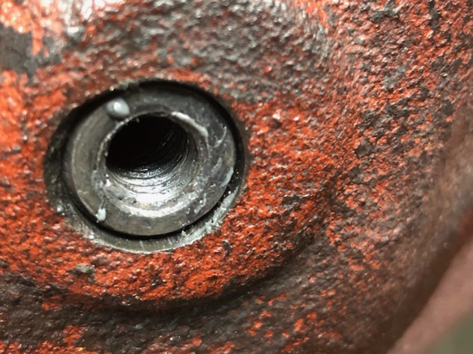
After eating lunch and regaining my composure, I take a look at the exploded view of the final drive, thinking maybe I left something out or didn't get something tight. I concluded there was no possible way that anything was missing or loose. I even double checked to make sure the keys were installed on the axle shaft where it couples to the rear wheel. Yep, all was good there.
I spun the removed LH final drive by hand - everything felt good. I rocked the other RH final sun gear shaft back and forth because the final housing was still installed, with the tire on the ground. All felt normal. Visions of checking myself into an insane asylum start to fill my head.
I figured something HAD to be slipping inside, so I grabbed the RH sun gear shaft one more time and gave it a really hard twist, and it moved, but the tire did not! I knew that the final drive gears were all good and in place, so I reasoned to myself that it could only be one other, very unlikely, thing - a slipping ring gear.
Now the problem is, the final is on the RH side, out of reach of my hoist. I envision putting the LH final and tire back on and trying to twist the entire assembly 180 degrees, and hurting or killing myself in the process (that whole thing is HEAVY!).
I then went and grabbed a 1.5 ton transmission jack, placed it under the drawbar hanger and PTO box, and cinched it down real tight with a chain and two straps. I lifted the whole rear axle housing off the ground, tires and all, then spun the whole works around so I could get at the RH final with my hoist.
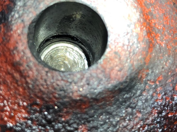
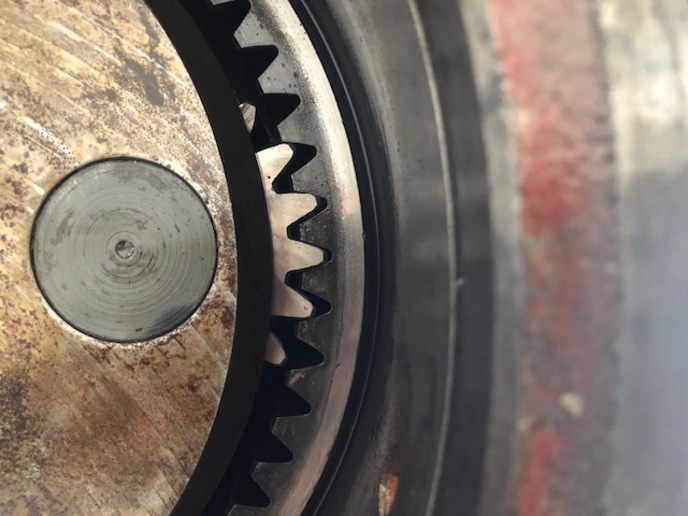
I pull the tire and final off, then the brakes. The ring gear appears normal, however I can spin it with a punch. Turns out there are 3 dowel pins that anchor it to the case, and each one of them had backed out. All I gotta do now is line the holes back up, drive the pins all the way back in, and figure out a way to keep them from backing out again. I had originally assumed that the pins broke, but that was not the case, they had simply backed out.
I bought this tractor after it had been sitting for 20 years because it all of a sudden "stopped moving". The former owner told me that it was diagnosed to him as a stripped SOS input shaft, and I had no way of verifying that because the engine was seized. After pulling the engine and then the tranny out, I discovered two things: 1) the SOS input shaft was not stripped, and 2) the rear axle disengagement coupler was not adjusted properly. Figuring that was the original problem all along, I went merrily on my way with the engine rebuild until I hopped in the seat the other day and put it in gear.
So, the original problem all this time was a slipping final drive ring gear. When's the last time you ever seen that on a Ford? Me neither!
I take out the rear axle fill plug and look inside with a flashlight. I can clearly see the pinion coupler spinning as I let the clutch out. I figure the problem HAS to be in the diffy because I've already been through both final drives when I put new axle shaft seals in earlier. I had to tear down the finals down to check and re-adjust the axle bearings, which were quite loose. I also put speedi-sleeves on the axle shafts.
Fortunately, the LH final is the one that has to come off to get at the diffy, and it's conveniently accessible with my overhead hoist. Off comes the rear tire, then the final (oops, nope, gotta split the thing to get the final off to clear the frame rail), then out comes the diffy. Everything looks fine, so I split the diffy in half, figuring the spider gear cross is cracked or some such thing. Everything looks perfect inside the diffy, right down to the "NAA" part numbers on the spider gears! At this point, I think I'm starting to lose my sanity, and that maybe I should change careers or something.
After eating lunch and regaining my composure, I take a look at the exploded view of the final drive, thinking maybe I left something out or didn't get something tight. I concluded there was no possible way that anything was missing or loose. I even double checked to make sure the keys were installed on the axle shaft where it couples to the rear wheel. Yep, all was good there.
I spun the removed LH final drive by hand - everything felt good. I rocked the other RH final sun gear shaft back and forth because the final housing was still installed, with the tire on the ground. All felt normal. Visions of checking myself into an insane asylum start to fill my head.
I figured something HAD to be slipping inside, so I grabbed the RH sun gear shaft one more time and gave it a really hard twist, and it moved, but the tire did not! I knew that the final drive gears were all good and in place, so I reasoned to myself that it could only be one other, very unlikely, thing - a slipping ring gear.
Now the problem is, the final is on the RH side, out of reach of my hoist. I envision putting the LH final and tire back on and trying to twist the entire assembly 180 degrees, and hurting or killing myself in the process (that whole thing is HEAVY!).
I then went and grabbed a 1.5 ton transmission jack, placed it under the drawbar hanger and PTO box, and cinched it down real tight with a chain and two straps. I lifted the whole rear axle housing off the ground, tires and all, then spun the whole works around so I could get at the RH final with my hoist.
I pull the tire and final off, then the brakes. The ring gear appears normal, however I can spin it with a punch. Turns out there are 3 dowel pins that anchor it to the case, and each one of them had backed out. All I gotta do now is line the holes back up, drive the pins all the way back in, and figure out a way to keep them from backing out again. I had originally assumed that the pins broke, but that was not the case, they had simply backed out.
I bought this tractor after it had been sitting for 20 years because it all of a sudden "stopped moving". The former owner told me that it was diagnosed to him as a stripped SOS input shaft, and I had no way of verifying that because the engine was seized. After pulling the engine and then the tranny out, I discovered two things: 1) the SOS input shaft was not stripped, and 2) the rear axle disengagement coupler was not adjusted properly. Figuring that was the original problem all along, I went merrily on my way with the engine rebuild until I hopped in the seat the other day and put it in gear.
So, the original problem all this time was a slipping final drive ring gear. When's the last time you ever seen that on a Ford? Me neither!