350 steering box reassembly

I'm reassembling the power steering box on my 350 after replacing a broken gear shaft. I've done this before semi successfully but the time I want to be 100% certain I'm doing it correctly.
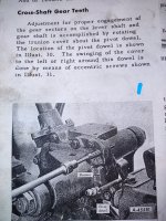
I'm not clear on how to properly adjust the two shafts, using the adjustment screws and eccentric screws when reassembling the two halves of the steering box. The instructions in the manual aren't clear to me. The are 2 sets of assembly instructions one for manual steering and one for power steering. In the middle of the PS steering instructions you are told to go to the manual steering section in order to make adjustments. The manual box is not identical to the PS box.

I've attached pictures of the instructions and my steering box. I've tried to highlight where appropriate and numbered the pages of the instructions so you can read.
My questions:
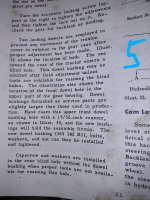
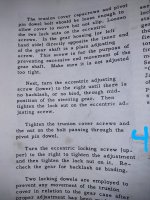
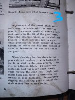
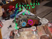
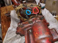
1. I don't understand how the screws circled in blue are properly adjusted. When turned inwards they will meet with the face of the opposing gear.

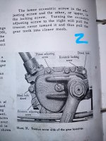
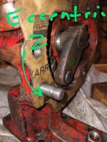
2. I don't understand how the eccentric screws highlighted in green are used to aid in the assembly/adjustment. The eccentric screw I marked number 2 doesn't appear to be eccentric or a screw. To me it is a.5 inch dowel with fine thread nuts on each end. Number 1 is screw and the shaft is eccentric.
Any feedback is appreciated.
Thanks Paul


3
 

Attachments

  • IMG_20240118_102822570~2.jpg
    IMG_20240118_102822570~2.jpg
    1.9 MB · Views: 21
  • IMG_20240118_102812852~2.jpg
    IMG_20240118_102812852~2.jpg
    1.9 MB · Views: 22
  • IMG_20240118_102750035~2.jpg
    IMG_20240118_102750035~2.jpg
    2.4 MB · Views: 23
  • IMG_20240118_102741696~2.jpg
    IMG_20240118_102741696~2.jpg
    2.9 MB · Views: 22
  • IMG_20240118_102722385~2.jpg
    IMG_20240118_102722385~2.jpg
    3.4 MB · Views: 26
  • IMG_20240118_102012524~2.jpg
    IMG_20240118_102012524~2.jpg
    2 MB · Views: 28
  • IMG_20240118_104305676~2.jpg
    IMG_20240118_104305676~2.jpg
    2.5 MB · Views: 23
  • IMG_20240118_101957173~2.jpg
    IMG_20240118_101957173~2.jpg
    2.4 MB · Views: 20
  • IMG_20240118_102012524~2.jpg
    IMG_20240118_102012524~2.jpg
    2 MB · Views: 21
Best I have (as the tractor vet says I am not there to look at it) But the images are clear.
The gears are designed to have near zero clearance when operating straight ahead. This means they are taller, away from the shaft centerline, on the middle teeth. The adjustment is originally made at the factory with two locating dowels, and eccentric screws. Only one dowel is used on reconstruction, the other is removed. The upper one labeled Dowel Hole, near the blue 2 on your image, is used to pivot the entire housing around that dowel, causing the two shafts to get closer or farther apart. The bolt holes for the housing are big enough to allow the housing to be fastened to the main casting in a range of positions. this range is sufficient to allow the gears to mesh with near zero clearance when correct within the adjustment range. There should be no binding when the gears are rotated through the center of their travel (straight ahead), but literally no play.
To do this, the eccentric screws (The eccentric adjusting screw is used to do this, then 2 ot three bolts are snugged up holding the position. Then tested for binding. When the adjustment is to your satisfaction, the remaining bolts are put in and all are tightened for final assembly. the eccentric screws are then held il=n location with a screw driver and the lock nut tightened on each. The shaft end play adjusters push the two shafts away from the screws and toward the housing that has the bushing in it. This limits end play in those shafts. The screws are adjusted so there is some resistance to rotation, then backed off until that resistance just disappears. (It is a finesse thing using less than an eighth turn of the screws) then held and locked down without turning. Jim
Jim, thank you once again. I've read this section in my manual many, many times. One problem is that I often don't know much of the vocabulary.. Sad to say I didn't know what an eccentric screw is! (Now I do). Looking at the parts diagram and the written instructions I I tried many combinations of assembling and adjusting trying to get the steering wheel to turn without drag or even working at all.

On the previous rebuilds I left as much as possible intact when I disassembled.This time I spent the time to remove all of the adjustment screws and get them to work smoothly. Apparently things were adjusted enough previously to allow some functionality on my previous rebuild. I did notice when I tore down this time that the new pin that runs up and down the spiral cam tube was already very worn. Apparently I severely over tightened those screws that move the shafts. Your explanation was very helpful filling in the blanks and confirming some steps I've taken. Long story short it's back together on my work bench and seems to be working fairly smooth!
That must be a relief. They are not intuitive. The adjustments can be exasperating. On my 350 (in about 1959) I drove it into a farm driveway (at about 12 mph) and across a frozen puddle about 8 inches deep. the puddle ice was only 3 inches, and it broke allowing the right front wheel to spear into the hole. The puddle was 15ft across, and the remaining ice did not break. the impact nearly through me off onto the ice to the right. The RF wheel twisted hard right snapping the steering arm off about mid arm. My dad was not a happy camper. I was too young to do the repair, but my dads cousin's son was a pro welder and he made it solid again so well the repair was not visible. It is still operating as repaired. Jim
 
That must be a relief. They are not intuitive. The adjustments can be exasperating. On my 350 (in about 1959) I drove it into a farm driveway (at about 12 mph) and across a frozen puddle about 8 inches deep. the puddle ice was only 3 inches, and it broke allowing the right front wheel to spear into the hole. The puddle was 15ft across, and the remaining ice did not break. the impact nearly through me off onto the ice to the right. The RF wheel twisted hard right snapping the steering arm off about mid arm. My dad was not a happy camper. I was too young to do the repair, but my dads cousin's son was a pro welder and he made it solid again so well the repair was not visible. It is still operating as repaired. Jim
I imagine Dad wasn't happy. That's was still a pretty new tractor!
This 350 hasn't had a lot of run time since I've owned it. I bought it for the loader but it starts right up and seems pretty solid. Steering was shot when I bought it and the trans had issues. Needs one more split to fix the seals that will prevent trans fluid seeping though to the dry clutch area. It was supposed to be fixed when I had the trans done but it slipped through the cracks during time when I wasn't there. Can't really complain the mechanic did a good deal of work including some welding and let me use his shop, lift, tools, etc. for not a lot of money. I'm waiting my turn now to get it's back in. I might skip this repair for awhile. I'll post in it soon. Thanks!
 

We sell tractor parts! We have the parts you need to repair your tractor - the right parts. Our low prices and years of research make us your best choice when you need parts. Shop Online Today.

Back
Top