Farmall H wiring

Sondanic

New User
Sorry for the redundant post but I’ve tried scouring other threads and haven’t gotten an exact answer. I recently inherited a Farmall H. Was told it last ran 6 years ago. I knew nothing about them initially and have taught myself little bits as I went along with working on it. It’s a 12v (new battery) 3 wire alternator. I’m not convinced the wiring is correct and I essentially need a diagram that’s so dumbed down a kindergartener could wire it up lol. Has a push button start, ignition switch, starter solenoid (3 terminal), I’m not sure how to tell if the coil is 12v or 6v but it’s the same one they used when it last ran so I imagine it will work (granted it’s still in working condition) but the wiring from coil to alternator/distributor is backwards from what other diagrams show so that’s been throwing me for a loop and it tried turning over when it was “wired backwards” and did nothing when I followed other diagrams wiring for the coil, resistor. Hope this is concise enough and thanks in advance! I should add I obviously have an ammeter, etc just figured that’s a given. My concern comes with the starter solenoid as no guide I’ve seen covers that in depth.
 
Last edited:
Here are the starter button and switch- also unsure how to wire those
image.jpg
image.jpg
image.jpg
 
Welcome to YT forums and PartsASAP.
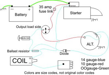
On this diagram, the starter has a saddle switch in stead of a solenoid. on yours, the solenoid is should be powered from a momentary contact push button switch. that switch gets its power from the starter side of the amp gauge. The bypass wire shown can be hooked to the big terminal on the saddle switch on the starter, and the ballast resistor as shown, but there must be a diode placed in the wire with the band end toward the ballast resistor to prevent back feeding the starter from the ignition.
The lights are supplied with voltage from the key side terminal on the amp meter.
The amp meter must be changed so the wires are on the opposite terminals to allow it to read correctly with negative ground.
Observe all polarities as shown. If you have more questions, ask. (I assume it is a Hitachi alternator), Note the marking equivalencies: if Hitachi, the S terminal is the same as the #2 on the diagram, and the L terminal is the same as #1 terminal. If it is not a 10SI or Hitachi, do not follow these instructions, let us know. Jim

c51194.jpg
 
Welcome to YT forums and PartsASAP.
On this diagram, the starter has a saddle switch in stead of a solenoid. on yours, the solenoid is should be powered from a momentary contact push button switch. that switch gets its power from the starter side of the amp gauge. The bypass wire shown can be hooked to the big terminal on the saddle switch on the starter, and the ballast resistor as shown, but there must be a diode placed in the wire with the band end toward the ballast resistor to prevent back feeding the starter from the ignition.
The lights are supplied with voltage from the key side terminal on the amp meter.
The amp meter must be changed so the wires are on the opposite terminals to allow it to read correctly with negative ground.
Observe all polarities as shown. If you have more questions, ask. (I assume it is a Hitachi alternator), Note the marking equivalencies: if Hitachi, the S terminal is the same as the #2 on the diagram, and the L terminal is the same as #1 terminal. If it is not a 10SI or Hitachi, do not follow these instructions, let us know. Jim

c51194.jpg
Thank you! I now have it cranking, but no spark. I’ve checked point and it’s opening/closing and clean. New spark plugs. Any ideas on that?
 
Hello Sd, welcome to YT! Here is another diagram that includes a starter solenoid.
6 to 12 volt diagram with 3 wire Delco 10SI
Since you have it cranking your concern with the solenoid may be lessened now. Does the tractor have lights on it, are they working or have they worked? I see the cover of the original light switch and ammeter mounting cover/plate, does it still have the original rotary light switch in it? I ask this because you have two toggle switches mounted in the horizontal section of the hydraulic rod support. This could indicate that it is wired with a second switch to energize the alternator excite circuit instead of using a diode or indicator bulb in the circuit. Any knowledge on what the second switch does? If one is a “momentary on” switch meaning it springs back to its original position when moved that could indicate its purpose is to energize the alternator and it would connect to the circuit going to the #1 spade terminal of the alternator.
the wiring from coil to alternator/distributor is backwards from what other diagrams show
Can you expand on what is backwards? Ignition coils will provide a spark even if not connected by proper polarity as in positive (+) and negative (-) when connected backwards they just are less efficient at providing a spark. A photo of the coil and distributor area would be helpful and the alternator as well. As for the ignition have you looked at the points? If you don’t have an automotive test light you should acquire one. With a test light you will be able to test for power to the coil (+)when the switch is on. If you have that then the opposite side (-) that goes to the distributor should not light the test lamp when the points are closed which shows the points are providing a ground for the coil. Most times when an engine is stopped the points are closed. Then conversely when the points are open the test light should should light. When all works properly for the most part with the points the test light connected to the distributor lead should flash off and on when the engine is cranking with the ignition on. The testing with the test light is completed with the “lead” or wire with the clamp on the end connected to a good ground or metal part of the tractor. A preliminary test when using a test light is to ground the lead and test it by probing on the positive battery post to ensure it lights.
 
Yesterday's Tractor Forums

We sell tractor parts! We have the parts you need to repair your tractor - the right parts. Our low prices and years of research make us your best choice when you need parts. Shop Online Today.

Back
Top