


I have a Ford 2120 that will turn over but won’t start. When I crank it over it shows no spark from the coil but as soon as I let up on the key ( it goes to run position) I get a spark. I’m not sure if I wired something up wrong, missing something minor or what but I can use any advice. It ran before but it ran rough. I tested the coil and it was weak so I did a complete tune up. Replaced coil, resistor, points, condenser, plugs, plug wires, distributor cap, and rotor. I couldn’t get it to start back up, wouldn’t even turn over, just clicked. Battery voltage was good and connections seemed good, but when I tested it showed I had a bad starter solenoid. Replaced the starter solenoid and now I have the problem I described at the first part of the post. I’m attaching a picture of how the starter system is wired. I know it doesn’t have the foot start or neutral safety but this is the way I bought it. Any help is appreciated.
You are using an out of date browser. It may not display this or other websites correctly.
You should upgrade or use an alternative browser.
You should upgrade or use an alternative browser.

Sean in PA
Well-known Member
There were a few Ford 2120 model tractors made over the years. The earliest was the ag chassis model in the 4 cylinder 2000 series made from 1963-1964. The second was the Highway chassis model in the 3 cylinder 2000 series made from 1965-1975. The third one was a 4 cylinder compact tractor made by Shibauru for Ford/New Holland from 1987-2003. It is always best to specify which one you are asking about. Given that the third one was only available as a diesel, I assume that is not the one that you are asking about.
Sean in PA
Well-known Member
After looking at your drawing, that does say 2120 4 cylinder gas tractor, so ignore my earlier post other than to please specify in the title of the thread or the text of you initial post in the future.
Looking at your drawing, there is a resistor in line with the coil. That indicates that the system was converted to 12 volts since that tractor was originally a 6 volt system. It also looks like the solenoid is now a newer automotive design with a case grounded primary, while the original had an isolated primary and the neutral safety starter switched originally provided the path to ground. Depending on which key switch is being used (since a key switch with a start position wasn't original to the tractor either) it is possible that the coil is only getting power when the key is in the run position and not the start position. Whether that key switch provides power to the run position while in the start position or not, you might try running a bypass wire from the starter side of the solenoid to the coil, bypassing the resistor, so that the coil gets the full 12 volts during starting. Once it starts and the key switch returns to the run position, the power to the coil will go through the resistor and protect the points and the coil as the ballast resistor is intended to do.
Looking at your drawing, there is a resistor in line with the coil. That indicates that the system was converted to 12 volts since that tractor was originally a 6 volt system. It also looks like the solenoid is now a newer automotive design with a case grounded primary, while the original had an isolated primary and the neutral safety starter switched originally provided the path to ground. Depending on which key switch is being used (since a key switch with a start position wasn't original to the tractor either) it is possible that the coil is only getting power when the key is in the run position and not the start position. Whether that key switch provides power to the run position while in the start position or not, you might try running a bypass wire from the starter side of the solenoid to the coil, bypassing the resistor, so that the coil gets the full 12 volts during starting. Once it starts and the key switch returns to the run position, the power to the coil will go through the resistor and protect the points and the coil as the ballast resistor is intended to do.

Keith Williams
Member
- Location
- Wellsville, Ohio
I concur on your assessment Sean. I would add that the correct solenoid may not be being used or he could have got the wrong one sold to him. My first thought was the same as yours, add a wire from the unused terminal on that solenoid to the + terminal of the coil.After looking at your drawing, that does say 2120 4 cylinder gas tractor, so ignore my earlier post other than to please specify in the title of the thread or the text of you initial post in the future.
Looking at your drawing, there is a resistor in line with the coil. That indicates that the system was converted to 12 volts since that tractor was originally a 6 volt system. It also looks like the solenoid is now a newer automotive design with a case grounded primary, while the original had an isolated primary and the neutral safety starter switched originally provided the path to ground. Depending on which key switch is being used (since a key switch with a start position wasn't original to the tractor either) it is possible that the coil is only getting power when the key is in the run position and not the start position. Whether that key switch provides power to the run position while in the start position or not, you might try running a bypass wire from the starter side of the solenoid to the coil, bypassing the resistor, so that the coil gets the full 12 volts during starting. Once it starts and the key switch returns to the run position, the power to the coil will go through the resistor and protect the points and the coil as the ballast resistor is intended to do.
Keith
After looking at your drawing, that does say 2120 4 cylinder gas tractor, so ignore my earlier post other than to please specify in the title of the thread or the text of you initial post in the future.
Looking at your drawing, there is a resistor in line with the coil. That indicates that the system was converted to 12 volts since that tractor was originally a 6 volt system. It also looks like the solenoid is now a newer automotive design with a case grounded primary, while the original had an isolated primary and the neutral safety starter switched originally provided the path to ground. Depending on which key switch is being used (since a key switch with a start position wasn't original to the tractor either) it is possible that the coil is only getting power when the key is in the run position and not the start position. Whether that key switch provides power to the run position while in the start position or not, you might try running a bypass wire from the starter side of the solenoid to the coil, bypassing the resistor, so that the coil gets the full 12 volts during starting. Once it starts and the key switch returns to the run position, the power to the coil will go through the resistor and protect the points and the coil as the ballast resistor is intended to do.
Jim.ME
Well-known Member
- Location
- central ME
To be clear on the suggested wire.

used red MN
Well-known Member
- Location
- Coon Rapids, MN
I have to respectfully disagree with this suggestion. Hopefully what Sean wrote and what he meant to say are two different things. By his description “the starter side of the solenoid” to me means the terminal lug that the heavy cable to the starter is connected as shown circled in red in my screen shot of the OP’s diagram. Connected as such when the key or starter switch is released from the start position the bypass wire would remain energized by the ignition circuit. This would attempt to continue to power the starter which would be a futile effort. That would likely cause the tractor not to run and ultimately burn out the bypass resistor. This setup would work with a diode in the circuit that would stop back-feed to the starter. However, considering his solenoid most likely contains the correct internal circuitry, Jim.ME’s diagram lays out what I agree to be the proper fix. I hope YT member with the initials TJ doesn’t see this thread!you might try running a bypass wire from the starter side of the solenoid to the coil, bypassing the resistor, so that the coil gets the full 12 volts during starting.

Thank you all for the good information. I've had to do a bit of "sorting out" since there are so many different suggestions, but thank you all. Now here is where I am at: Before placing the jumper on the terminals I tested for voltage at the coil to see if there was voltage both during "START" and in the "RUN" position. I had 12V in both positions. I used my spark tester to see if there was any spark from the distributor or the coil and neither had spark. I opened the distributor and found I had 12V to the movable side of the points (in both "RUN" and "START", however I would only get a spark across the points when I released the key back to the "RUN" position. In my thinking this would tell me I have a bad "capacitor" because it is supposed to charge while points are closed and discharge when the points open (high side of the cam rotations) which would create the spark. Does this sound correct or do you think I am way off base.
Sean in PA
Well-known Member
deleted
Sean in PA
Well-known Member
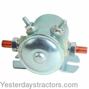
We have no idea. The OP didn't specify a part number for the solenoid that he ordered. We're not eve sure that it's electrically the same as the one he replaced, whatever type that was.
|
Yes, it is and I think it may be the wrong one. See the thread I just posted.We have no idea. The OP didn't specify a part number for the solenoid that he ordered. We're not eve sure that it's electrically the same as the one he replaced, whatever type that was.
Jim.ME
Well-known Member
- Location
- central ME
Looking at your drawing, I do not see how using a key switch would energize that solenoid, if it is an is an isolated base solenoid. You have posted the starter turned the engine over, so it must have a grounded base.
No spark when cranking sounds like a switch problem to me. Try putting the jumper wire on and see what happens.
What brand and part number solenoid do you have installed right now, not what it might be.
No spark when cranking sounds like a switch problem to me. Try putting the jumper wire on and see what happens.
What brand and part number solenoid do you have installed right now, not what it might be.
used red MN
Well-known Member
- Location
- Coon Rapids, MN
Your theory of operation of the condenser is incorrect. The ignition coil charges when the points are closed. And when the magnetic field in the primary windings drops off when the points open the field collapses into nearby secondary winding producing the spark. Secondly, although it is a “spark” you see across the point contacts in reality it is an “arc”. This is one of the most misconceived items of a points style ignition. The arc you see there doesn’t have a real correlation to the spark traveling out of the coil through the distributor and on to the plug wires. With a test meter on the volt scale or a simple test light connecting to terminal lead out of the distributor with the ignition on when the points are closed it should read zero volts (or nearly) because when functioning properly the points contact it to ground. Conversely, it should show system voltage when open. The condenser is limiting the arc across the points when they open. Any charge that develops in the condenser bleeds back into the primary circuit in mere milliseconds something you can only see on an oscilloscope.I opened the distributor and found I had 12V to the movable side of the points (in both "RUN" and "START", however I would only get a spark across the points when I released the key back to the "RUN" position. In my thinking this would tell me I have a bad "capacitor" because it is supposed to charge while points are closed and discharge when the points open (high side of the cam rotations) which would create the spark.
used red MN
Well-known Member
- Location
- Coon Rapids, MN
So the solenoid is cranking the engine, correct? If so what you need to do before throwing the towel in on that solenoid test the small terminal that you show no connection to in your diagram for voltage while cranking and none otherwise. If it shows voltage while cranking add a circuit connecting it as shown in Jim’s diagram. Start it up and tractor on…!!Yes, it is and I think it may be the wrong one. See the thread I just posted.
So….after all the fuss and frustration I’m kicking myself in the butt. I had read in some of the other Ford forums where they have been seeing bad capacitors straight off the shelf. Well I figured that couldn’t be the case with mine, after all it came with a brand new complete tune up kit…. Well guess what… I put the old capacitor back in just because I was out of ideas and bam! She fired right up and purring like a kitten… thanks again for all the support.

We sell tractor parts! We have the parts you need to repair your tractor - the right parts. Our low prices and years of research make us your best choice when you need parts. Shop Online Today.
Copyright © 1997-2025 Yesterday's Tractor Co.
All Rights Reserved. Reproduction of any part of this website, including design and content, without written permission is strictly prohibited. Trade Marks and Trade Names contained and used in this Website are those of others, and are used in this Website in a descriptive sense to refer to the products of others. Use of this Web site constitutes acceptance of our User Agreement and Privacy Policy TRADEMARK DISCLAIMER: Tradenames and Trademarks referred to within Yesterday's Tractor Co. products and within the Yesterday's Tractor Co. websites are the property of their respective trademark holders. None of these trademark holders are affiliated with Yesterday's Tractor Co., our products, or our website nor are we sponsored by them. John Deere and its logos are the registered trademarks of the John Deere Corporation. Agco, Agco Allis, White, Massey Ferguson and their logos are the registered trademarks of AGCO Corporation. Case, Case-IH, Farmall, International Harvester, New Holland and their logos are registered trademarks of CNH Global N.V.
Yesterday's Tractors - Antique Tractor Headquarters
Website Accessibility Policy