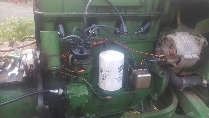
After splitting my Oliver Super 55 to replace the PTO clutch and pilot bearing, I have decided to replace the old wiring. I am struggling with how to hook up the Alternator and Voltage regulator. The system was working fine before I took it all apart. It is comprised of an alternator (Delco- Remy) and an external Voltage Regulator.
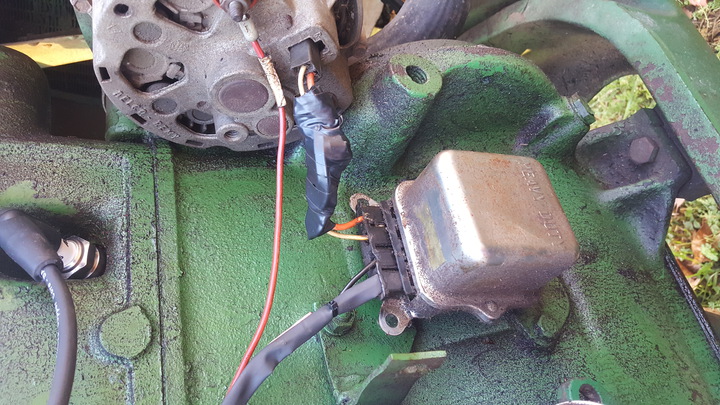
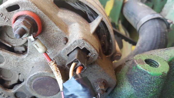
The wiring harness for the alternator to the voltage regulator stayed untouched. The Field terminal on the Alt goes to the F terminal on the Voltage Regulator. The R terminal goes to the #2 terminal on the voltage regulator. One of the leads has a diode on it. I don?t recall which on.
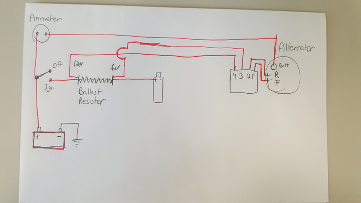
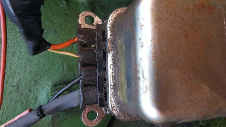
My question is where does #3 and #4 from the regulator go. If memory serves me right, they went to the ends of the ballast resistor. I don?t recall which went to what end on the resistor. I believe the right way is #3 goes to the resisted side (6v) of the Ballast resistor and #4 went to unresisted side of the resistor (12v).
Does this make sense? Is it backwards? I have attached photos of the parts and a diagram I drew up.
The wiring harness for the alternator to the voltage regulator stayed untouched. The Field terminal on the Alt goes to the F terminal on the Voltage Regulator. The R terminal goes to the #2 terminal on the voltage regulator. One of the leads has a diode on it. I don?t recall which on.
My question is where does #3 and #4 from the regulator go. If memory serves me right, they went to the ends of the ballast resistor. I don?t recall which went to what end on the resistor. I believe the right way is #3 goes to the resisted side (6v) of the Ballast resistor and #4 went to unresisted side of the resistor (12v).
Does this make sense? Is it backwards? I have attached photos of the parts and a diagram I drew up.