

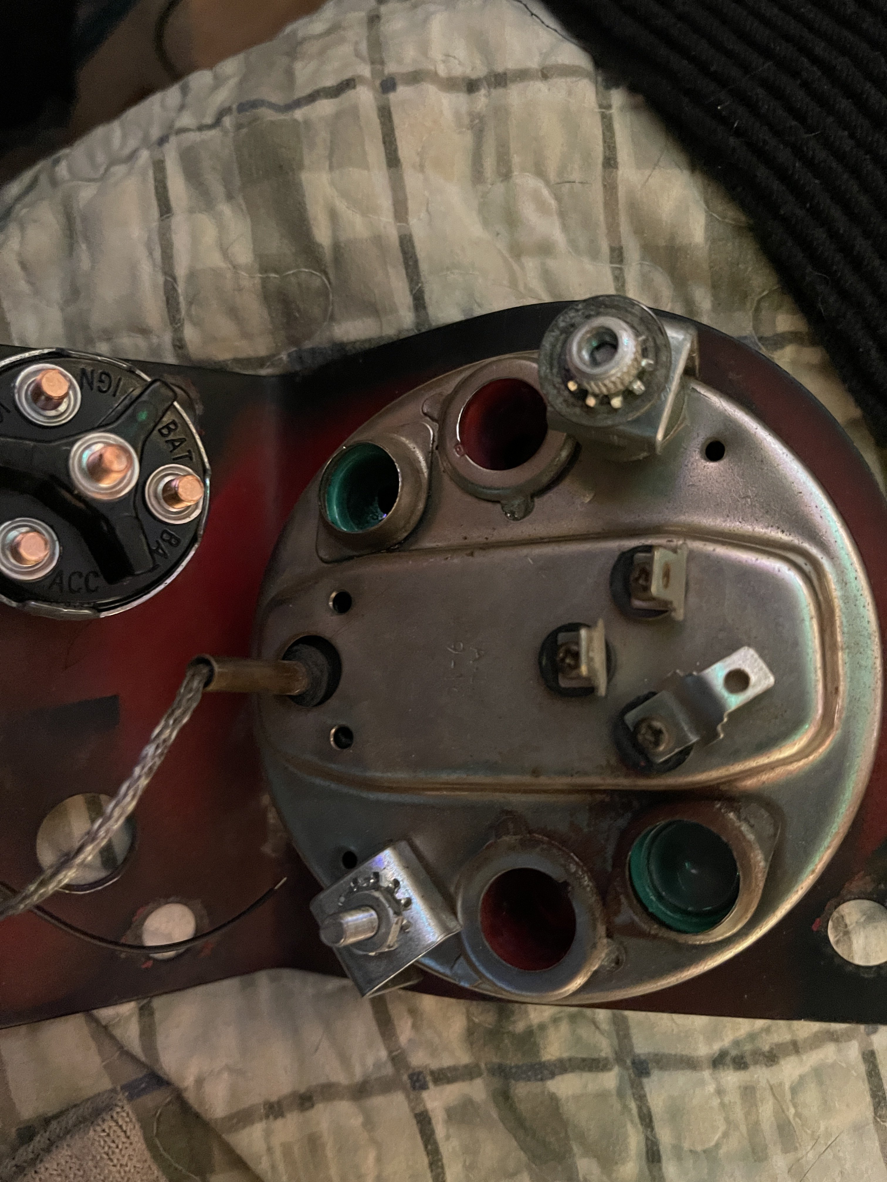
Any help on understanding this panel wiring?

>Tractor is an IH/farmall 826 diesel.
> I am rewiring the tractor and swapping the POS 3 wire/external regulated alternator for a delco 10si/internally regulated alternator
>photos are of right hand panel instrument cluster/gauge thingies


I've already tried looking in literature for the tractor, but as usual, and always, the operator's manual/service&repair manual are just below the threshold of actually being useful. There's no markings on the gauges whatsoever, and original wiring had literally deteriorated into nothing and was so janky with splicing photos wouldn't even help

1) The main part of this panel I need info on is the AMP light

2) is this amp gauge actually just an idiot light for detecting (any) amperage at all (make sure that the battery is getting charged)? As it's just a light rather than a true gauge (im assuming the bottom gauge is for the oil pressure, though maybe I'm wrong?

3) I have an
Aftermarket voltage meter gauge

I've swapped the air filter indicator for the voltage gauge, but im not sure how to wire it in properly. Ive read that a voltage meter is superior to amp gauges and makes them unnecessary, but I can't find any videos or instructions on how to do so

IMG_6206.jpeg
 

Attachments

  • IMG_6207.jpeg
    IMG_6207.jpeg
    1.8 MB · Views: 157
Solution
Does it make sense if it still turned over when wired as i stated above? I wasnt able to/didnt try to get it to fully turn on (its like -5F outside and i am tired). Or would it still turn the starter but be wrong or damaging as left?

It is this alternator i bought

stein
Er
Tractor

ABC6206-63-Amp-One-Wire-Fast-Start-Alternator-with-Pulley

Site keeps changing the url for some reason so i cant post directly but it comes up easy on google
That really helps!!! The wiring I have suggested can basically be ignored. There os only one wire needed and that is from the Bat on the Alt to the battery post where you have it. The #1 and #2 terminals are to be ignored. This style of alternator does use a tiny amount of electricity all the...
From the bat terminal on your alternator you should just run a 10 ga wire directly to the post on the starter where the positive battery cable connects. You can do this since you are not using an ammeter otherwise the wire off the alt would need to go up to the dash. A little short 16ga jumper from the bat terminal on the alt over to the “2” spade on the edge of the 10si. The number “1” spade needs to connect to the ignition switch. This will work fine on a diesel with a throttle kill.
Your voltmeter will also just need to have power when the ignition is on. It may have a light to illuminate the dial that will have to connect to the light wiring.
The gauge in the cluster gauge you are showing opposite of the fuel gauge is the temp gauge that operates by a manual capillary tube. Those tractors only had an idiot “tell tale” light for oil pressure. If I had a proper wiring diagram I think the amp light could be connected to the “1” spade on the alternator and work like a charge lamp. I do not want to mislead you. I have a wiring diagram for the “..06” series which I think is close. I will wait and see if someone post one for the “..26/..56” series.
 
Upvote 0
The tell light was also hooked into the oil pressure for the TA or something like that on some of them so it would blink when you stepped on the clutch. Since my wire broke off decades ago and the tractor didn't have a TA I never worried about the sending unit on the MCV with oil pressure. This was the set up for the 06,56,26,and I believe the 66 series tractors in the bigger row crop models of the 706,756,766 and bigger. Never was around any of the smaller ones of those vintages other than the 74 series. And those were the English made models and a lot different arrangement.
 
Upvote 0
From the bat terminal on your alternator you should just run a 10 ga wire directly to the post on the starter where the positive battery cable connects. You can do this since you are not using an ammeter otherwise the wire off the alt would need to go up to the dash. A little short 16ga jumper from the bat terminal on the alt over to the “2” spade on the edge of the 10si. The number “1” spade needs to connect to the ignition switch. This will work fine on a diesel with a throttle kill.
Your voltmeter will also just need to have power when the ignition is on. It may have a light to illuminate the dial that will have to connect to the light wiring.
The gauge in the cluster gauge you are showing opposite of the fuel gauge is the temp gauge that operates by a manual capillary tube. Those tractors only had an idiot “tell tale” light for oil pressure. If I had a proper wiring diagram I think the amp light could be connected to the “1” spade on the alternator and work like a charge lamp. I do not want to mislead you. I have a wiring diagram for the “..06” series which I think is close. I will wait and see if someone post one for the “..26/..56” series.
Treat the Amp light like the warning light or diode in your typical 3-wire 12V conversion for the old Farmalls.

You don't NEED the ammeter but you could add one.

https://www.yesterdaystractors.com/articles/artint195.htm

12valt.jpg
 
Upvote 0
The tell light was also hooked into the oil pressure for the TA or something like that on some of them so it would blink when you stepped on the clutch. Since my wire broke off decades ago and the tractor didn't have a TA I never worried about the sending unit on the MCV with oil pressure. This was the set up for the 06,56,26,and I believe the 66 series tractors in the bigger row crop models of the 706,756,766 and bigger. Never was around any of the smaller ones of those vintages other than the 74 series. And those were the English made models and a lot different arrangement.
That's on the 06 series only.

On the 826 there's a separate light down on the panel for the clutch/TA/MCV lube pressure tellight. The oil light on the gauge is for engine oil pressure only.
 
Upvote 0
Any light used for the 3 wire Delco alternator needs to be in series with the #1 terminal to keyed ignition (on) voltage. The existing light may be grounded and have one wire. There are many sources for 2 wire 12v indicator lights. The diagram shown shows this series circuit. Jim
 
Upvote 0
Any light used for the 3 wire Delco alternator needs to be in series with the #1 terminal to keyed ignition (on) voltage. The existing light may be grounded and have one wire. There are many sources for 2 wire 12v indicator lights. The diagram shown shows this series circuit. Jim
this isnt a 3 wire/ext reg anymore tho, the new alternator is internally regulated
 
Upvote 0
From the bat terminal on your alternator you should just run a 10 ga wire directly to the post on the starter where the positive battery cable connects. You can do this since you are not using an ammeter otherwise the wire off the alt would need to go up to the dash. A little short 16ga jumper from the bat terminal on the alt over to the “2” spade on the edge of the 10si. The number “1” spade needs to connect to the ignition switch. This will work fine on a diesel with a throttle kill.
Your voltmeter will also just need to have power when the ignition is on. It may have a light to illuminate the dial that will have to connect to the light wiring.
The gauge in the cluster gauge you are showing opposite of the fuel gauge is the temp gauge that operates by a manual capillary tube. Those tractors only had an idiot “tell tale” light for oil pressure. If I had a proper wiring diagram I think the amp light could be connected to the “1” spade on the alternator and work like a charge lamp. I do not want to mislead you. I have a wiring diagram for the “..06” series which I think is close. I will wait and see if someone post one for the “..26/..56” series.
this is all of the diagrams i have had to work off of, probably same as what you had. the 06 seems to be close enough i would take your advice if you're willing to share it
 

Attachments

  • 595075a6c081d_scan0005(Large).jpg.3839d2b03cfe656ac1d0e495112f2371.jpg
    595075a6c081d_scan0005(Large).jpg.3839d2b03cfe656ac1d0e495112f2371.jpg
    205.5 KB · Views: 147
  • 5950773fe0686_scan0002(Large).jpg.b5e832569d7d8204f65f93ff6456667a.jpg
    5950773fe0686_scan0002(Large).jpg.b5e832569d7d8204f65f93ff6456667a.jpg
    163.7 KB · Views: 228
  • 5950780be2eef_scan0006(Large).jpg.71311f7d45a96086980bcda1e1c87c57.jpg
    5950780be2eef_scan0006(Large).jpg.71311f7d45a96086980bcda1e1c87c57.jpg
    87.8 KB · Views: 236
  • PDF document.pdf
    PDF document.pdf
    247.2 KB · Views: 75
Upvote 0
this isnt a 3 wire/ext reg anymore tho, the new alternator is internally regulated
The original external regulator should be entirely disconnected. My discussion is aimed at the internally regulated Delco alternator. The #1 terminal on that alternator, connected as follows when installed in a vehicle it was designed for originally. The Key switch on the vehicle, when turned on, provides battery voltage to accessories and devices including the dash "idiot" light for the alternator. The light is thus supplied battery voltage. The light in the dash is not grounded, it is attached to #1 terminal on the alternator. That alternator terminal is electronically grounded in the internal voltage regulator. The light on the dash now comes on before the vehicle is started. When the vehicle starts, the alternator's internal regulator recognizes the signal of voltage coming through the light circuit, and that turns on the alternator rotor voltage creating charge out the big terminal. The regulator now changes the #1 terminal from a ground to a 12v+ source of voltage (electronically). now the dash 'idiot' light has 12+ volts applied to both leads going into its filament. because it has the same voltage on both leads, and no ground the lamp goes out. To the operator, this means the alternator is working correctly. If the alternator fails, this #1 terminal is supposed to go back to a ground state, making the light come on warning the operator that the charging system has failed. If the circuit has no light (or diode, or 10 ohm resistor) the turning alternator keeps sending out 12+ volts to the On or off ignition Key. this keeps the engine running even with the key off. I hope this helps. Jim
 
Upvote 0
Here is a wiring diagram for the ..06 series. I can only believe that it may be somewhat helpful to you. Please keep in mind that I have no idea how similar the two models were wired. As barnyard pointed out above the oil pressure light was different between the two. So keep in mind when using it there will be some amount of “interpretation” needed.
..06 series wiring diagram
 
Upvote 0
The original external regulator should be entirely disconnected. My discussion is aimed at the internally regulated Delco alternator. The #1 terminal on that alternator, connected as follows when installed in a vehicle it was designed for originally. The Key switch on the vehicle, when turned on, provides battery voltage to accessories and devices including the dash "idiot" light for the alternator. The light is thus supplied battery voltage. The light in the dash is not grounded, it is attached to #1 terminal on the alternator. That alternator terminal is electronically grounded in the internal voltage regulator. The light on the dash now comes on before the vehicle is started. When the vehicle starts, the alternator's internal regulator recognizes the signal of voltage coming through the light circuit, and that turns on the alternator rotor voltage creating charge out the big terminal. The regulator now changes the #1 terminal from a ground to a 12v+ source of voltage (electronically). now the dash 'idiot' light has 12+ volts applied to both leads going into its filament. because it has the same voltage on both leads, and no ground the lamp goes out. To the operator, this means the alternator is working correctly. If the alternator fails, this #1 terminal is supposed to go back to a ground state, making the light come on warning the operator that the charging system has failed. If the circuit has no light (or diode, or 10 ohm resistor) the turning alternator keeps sending out 12+ volts to the On or off ignition Key. this keeps the engine running even with the key off. I hope this helps. Jim
Can you explain how to wire the key switch to the push button? None of the diagrams help because of volt voltage regulator confusing everything up.

So right now I have

1) Batt terminal on alt -->starter post (same as + battery cable)

2) Positive battery terminal cable --> starter post (same as alt)

3) (IH style) Key switch/right side --> "start" terminal post on the starter solenoid

4) key switch/left side --> push button starter/right side

5) push button/left side --> starter post (same terminal as the battery cable and wire from batt post on alternator)


Also, i don't really understand anything about the two terminals under the plug on the alternator. I keep getting conflicting information about whether they're needed or not. Right now i have the #2/right side spade terminal connected via jumper wire to the batt terminal on the alternator. Closest i can understand is that doing so allow you to not need a diode (no idea what this is either) to excite (still clueless) the alternator, and prevent the alternator from draining the battery even when key switch is off?

As for the left hand spade terminal it is supposed to be so you can attach a warning/idiot light? Currently i have nothing connected to it. I do have one that i bought but dont know how that works either. It has 2 terminals, one of which goes to the alternator i suppose, but i don't know about where the second one goes to.
Is this correct?
 
Last edited:
Upvote 0
Can you explain how to wire the key switch to the push button? None of the diagrams help because of volt voltage regulator confusing everything up.

So right now I have

1) Batt terminal on alt -->starter post (same as + battery cable)

2) Positive battery terminal cable --> starter post (same as alt)

3) (IH style) Key switch/right side --> "start" terminal post on the starter solenoid

4) key switch/left side --> push button starter/right side

5) push button/left side --> starter post (same terminal as the battery cable and wire from batt post on alternator)


Also, i don't really understand anything about the two terminals under the plug on the alternator. I keep getting conflicting information about whether they're needed or not. Right now i have the #2/right side spade terminal connected via jumper wire to the batt terminal on the alternator. Closest i can understand is that doing so allow you to not need a diode (no idea what this is either) to excite (still clueless) the alternator, and prevent the alternator from draining the battery even when key switch is off?

As for the left hand spade terminal it is supposed to be so you can attach a warning/idiot light? Currently i have nothing connected to it. I do have one that i bought but dont know how that works either. It has 2 terminals, one of which goes to the alternator i suppose, but i don't know about where the second one goes to.
Is this correct?
You need to swap the connection points of 3 and 5. The right side of your key switch needs to go to the large solenoid battery terminal where the battery cable and alternator feed are connected. The push button left side needs to go to the S or “start” terminal on the solenoid. You will also need to have a power lead coming off the left side of the key switch to operate the instruments as needed. In particular the fuel gauge.
Was your alternator sold as a “one wire” or is it just an over the shelf automotive alternator? You say it has a plug cover on the 1/2 spade tabs? That is how “one wire” alternators come. If it is a one wire it may not need connections to the side spades.
 
Upvote 0
Can you explain how to wire the key switch to the push button? None of the diagrams help because of volt voltage regulator confusing everything up.

So right now I have

1) Batt terminal on alt -->starter post (same as + battery cable)

2) Positive battery terminal cable --> starter post (same as alt)

3) (IH style) Key switch/right side --> "start" terminal post on the starter solenoid

4) key switch/left side --> push button starter/right side

5) push button/left side --> starter post (same terminal as the battery cable and wire from batt post on alternator)


Also, i don't really understand anything about the two terminals under the plug on the alternator. I keep getting conflicting information about whether they're needed or not. Right now i have the #2/right side spade terminal connected via jumper wire to the batt terminal on the alternator. Closest i can understand is that doing so allow you to not need a diode (no idea what this is either) to excite (still clueless) the alternator, and prevent the alternator from draining the battery even when key switch is off?

As for the left hand spade terminal it is supposed to be so you can attach a warning/idiot light? Currently i have nothing connected to it. I do have one that i bought but dont know how that works either. It has 2 terminals, one of which goes to the alternator i suppose, but i don't know about where the second one goes to.
Is this correct?
Being a diesel, The #2 terminal is correct wired to the Bat terminal with a short wire.
The Bat terminal is correct attached to the starter where the Battery positive cable attaches to a big stud. (10 gauge wire)
The #1 terminal can be attached directly to a 2 wire 12v indicator light on the dash (yours to purchase and install). then from that new "idiot" light to the IGN terminal on the key, The light is needed because the diesel is shut off by fuel not electricity, and the light will remind you to shut off the key. If the key is left on the alternator will be left on and a battery drain will happen (slowly but surely).
An alternative to the Key switch being used is to use an oil pressure switch from NAPA to cause the alternator to start and stop. This switch is cheap, and will plumb into the port that has the oil pressure sending unit in it. (could be a tube if the gauge is non-electric). You would need a nipple and T so the gauge works and the switch gets pressure. One of the two terminals on the switch (either) connects to the Battery post on the starter where the Bat wire is attached, the other terminal is connected to the #1 terminal of the alternator. This does not need a light but could have one in series with that wire to the pressure switch if you wanted a "idiot" light for the alternator functioning. The oil pressure switch shuts off the alternator when the engine stops. Jim
 
Upvote 0
You need to swap the connection points of 3 and 5. The right side of your key switch needs to go to the large solenoid battery terminal where the battery cable and alternator feed are connected. The push button left side needs to go to the S or “start” terminal on the solenoid. You will also need to have a power lead coming off the left side of the key switch to operate the instruments as needed. In particular the fuel gauge.
Was your alternator sold as a “one wire” or is it just an over the shelf automotive alternator? You say it has a plug cover on the 1/2 spade tabs? That is how “one wire” alternators come. If it is a one wire it may not need connections to the side spades.
Does it make sense if it still turned over when wired as i stated above? I wasnt able to/didnt try to get it to fully turn on (its like -5F outside and i am tired). Or would it still turn the starter but be wrong or damaging as left?

It is this alternator i bought

stein
Er
Tractor

ABC6206-63-Amp-One-Wire-Fast-Start-Alternator-with-Pulley

Site keeps changing the url for some reason so i cant post directly but it comes up easy on google
 
Upvote 0
Does it make sense if it still turned over when wired as i stated above? I wasnt able to/didnt try to get it to fully turn on (its like -5F outside and i am tired). Or would it still turn the starter but be wrong or damaging as left?

It is this alternator i bought

stein
Er
Tractor

ABC6206-63-Amp-One-Wire-Fast-Start-Alternator-with-Pulley

Site keeps changing the url for some reason so i cant post directly but it comes up easy on google
That really helps!!! The wiring I have suggested can basically be ignored. There os only one wire needed and that is from the Bat on the Alt to the battery post where you have it. The #1 and #2 terminals are to be ignored. This style of alternator does use a tiny amount of electricity all the time. We had no idea it was other than a standard 10SI. No need to change the key, or lights! The old regulator can be removed and all wires there taped up or terminated with a wire nut on each. Woof. Jim
 
Upvote 0
Solution
Does it make sense if it still turned over when wired as i stated above? I wasnt able to/didnt try to get it to fully turn on (its like -5F outside and i am tired). Or would it still turn the starter but be wrong or damaging as left?

It is this alternator i bought

stein
Er
Tractor

ABC6206-63-Amp-One-Wire-Fast-Start-Alternator-with-Pulley

Site keeps changing the url for some reason so i cant post directly but it comes up easy on google
Yes, it makes sense that it turned over. But any other circuit such as the fuel gauge would not work. It would only have power while you’re pushing the start button.
 
Upvote 0
Does it make sense if it still turned over when wired as i stated above? I wasnt able to/didnt try to get it to fully turn on (its like -5F outside and i am tired). Or would it still turn the starter but be wrong or damaging as left?

It is this alternator i bought

stein
Er
Tractor

ABC6206-63-Amp-One-Wire-Fast-Start-Alternator-with-Pulley

Site keeps changing the url for some reason so i cant post directly but it comes up easy on google

The site keeps changing the link when you try to post it because you are not supposed to be promoting competitor's sites here. Steiner sells parts and is a competitor of YT and their parent company All States Ag Parts.
 
Upvote 0
That really helps!!! The wiring I have suggested can basically be ignored. There os only one wire needed and that is from the Bat on the Alt to the battery post where you have it. The #1 and #2 terminals are to be ignored. This style of alternator does use a tiny amount of electricity all the time. We had no idea it was other than a standard 10SI. No need to change the key, or lights! The old regulator can be removed and all wires there taped up or terminated with a wire nut on each. Woof. Jim
So as for powering anything else (lights) etc, would i be able to run a 8-10 gauge wire to the terminal block and from there, run wires to various things (ether solenoid, light switches, etc)?

For example, for the ether button/solenoid

Hot wire from junction block --> one side of ether switch button (or to in-line fuse/breaker, then to the button, unless unnecessary)

Other side of ether button --> to the top of the ether dispenser/solenoid thingy

Other terminal connection on solenoid --> grounded to frame

And for the light switch i was going to buy these

YETOR Waterproof Extension Cable 4Pin,16AWG Extension Lead Waterproof Cord,IP68 Extension Cable for Solar Spotlights,Garden Spike Lights,LED Strip Lights (4pin 9.84FT) https://a.co/d/cR2gyPH

YETOR Waterproof Connector 4 Wire,16AWG Male Female Plug LED Connector Witch 4Pin Waterproof Connectors IP68 with 20CM Extension Cable for Indoor/Outdoor LED Strip Lights.(5Pairs) https://a.co/d/ftP2PJg

I would just attach spade connectors onto the end of on of the connectors, and then use an extension cable or two to plumb the cabling throughout the cab to replace the old 4 wire/bullet style that's currently in place. Is 16 awg large enough though?
 
Upvote 0
So as for powering anything else (lights) etc, would i be able to run a 8-10 gauge wire to the terminal block and from there, run wires to various things (ether solenoid, light switches, etc)?

For example, for the ether button/solenoid

Hot wire from junction block --> one side of ether switch button (or to in-line fuse/breaker, then to the button, unless unnecessary)

Other side of ether button --> to the top of the ether dispenser/solenoid thingy

Other terminal connection on solenoid --> grounded to frame

And for the light switch i was going to buy these

YETOR Waterproof Extension Cable 4Pin,16AWG Extension Lead Waterproof Cord,IP68 Extension Cable for Solar Spotlights,Garden Spike Lights,LED Strip Lights (4pin 9.84FT) https://a.co/d/cR2gyPH

YETOR Waterproof Connector 4 Wire,16AWG Male Female Plug LED Connector Witch 4Pin Waterproof Connectors IP68 with 20CM Extension Cable for Indoor/Outdoor LED Strip Lights.(5Pairs) https://a.co/d/ftP2PJg

I would just attach spade connectors onto the end of on of the connectors, and then use an extension cable or two to plumb the cabling throughout the cab to replace the old 4 wire/bullet style that's currently in place. Is 16 awg large enough though?
Due to your wiring prowess (this means less than adequate knowledge) I would suggest as you continue this endeavor that you place a temporary fuse in the connection between the positive battery cable terminal on the solenoid and the wire (mentioned in 5 above) which I directed you to hook it on the key switch. This fuse should also protect the proposed connection to the junction block. Yes what you are proposing with the J block will work. I personally would not connect the either dispenser to a power supply that is always energized. I would connect it to only be powered when the key is on. If there is ever any chance a kid will get on this thing and mess around the next start after that may give you a huge unwanted surprise. After you have completed your wiring I would suggest replacing the temporary fuse with a fusible link section as I have attached.
Fusible link
 
Upvote 0
Yesterday's Tractor Forums

We sell tractor parts! We have the parts you need to repair your tractor - the right parts. Our low prices and years of research make us your best choice when you need parts. Shop Online Today.

Back
Top
