Battery chargers - Geo will love this

kencombs

Well-known Member
Link to an old Mopar board where I spend some time. One of the members found this battery charger and the unique mod some previous owner did.
https://p15-d24.com/topic/60234-cool-vintage-battery-charger/

Lots of older chargers had no way of controlling rate but not a problem for him. Or her.
 
I've never seen a charger with a coil to reduce output.
I would like to know if the coil's impedance is at play here. It will be interesting to measure the ohms of the coil..

I have used headlight and tail light bulbs to reduce current to turn a charger into a trickle charger to charge small batteries on my kid's toys.
 
(quoted from post at 18:50:57 07/16/23) I've never seen a charger with a coil to reduce output.

I'd GUESS that's a big tapped resistor and NOT a ''coil'', YAMMV!

NOT much use for ''impedance'' in a DC circuit!
 
NOT much use for ''impedance'' in a DC circuit!

wore out,
Did you know the frequency of the battery charger
output is 120 hz and an AC amprobe can measure
the current because the output is changing DC
current???

Use any meter that can measure frequency and AC
current, then post back your findings.
 
Fun info and pics, thanks Ken, I like some of the old fashion chargers and other equipment like the old Sun diagnostics. At tractor shows I exhibit some of my older analog electric testing equipment, its well received and I get lots of fun questions and comments..

All you great sparkies here already know this, but FYI for others concerning older battery chargers (NOT modern regulated smart chargers) below is MY opinion based on oldddddddd memory lol so no warranty but believe it's still accurate:

When they RECTIFY the 120 VAC 60 Hz AC (probably using Full Wave rectification or maybe Half Wave ?) the result obtained is a PULSING DC with frequency like the AC input. Its NOT any smooth perfect level DC, HOWEVER its still DC albeit pulsing and can still charge a battery.

If a smooth level DC were needed, the pulsing DC could be FIILTERED using Inductors and Capacitors (anyone remember studying and building Butterworth Filters ?)

It would be my GUESS that big coil looking device works like a big variable resistor (coils still have resistance) with taps along different locations which would, of course, yield different voltages which in turn yield different charge rates into the battery.

HOWEVER even if little (as compared to a more complex filter of capacitors and inductors) a Coil which is an Inductor still with resistance on the Pulsing DC output could provide some small degree of filtering, BUT I SEE ITS USE PRIMARILY AS A VARIABLE TAP CHANGE RESISTOR TO ADJUST CHARGE RATE

There ya go that MY BEST RECOLLECTION and MY opinion, Im never too old to learn so any additions and/or corrections are sure welcome so we can alllllllll learn and help our fellow old tractor lovers..

Best wishes to everyone here..

John T NOT any battery charger expert but still ever curious to learn
 
Kinda like this, except 120 Hz
mhRMX0H.jpg
and a variac will make your charger input completely variable from 0 to 120v +.
7nMd2AT.jpg

8fUF39C.jpg


This post was edited by JMOR on 07/17/2023 at 07:52 am.
 
Jessie
Yes 120 hz
What do you think the voltage divider is
made of?
I think it's coils of wire which has
impedance.
What say you?
 
(quoted from post at 12:41:49 07/17/23) Jessie
Yes 120 hz
What do you think the voltage divider is
made of?
I think it's coils of wire which has
impedance.
What say you?
ell it being a coil, it will have both resistance and inductance, ...but the controlling factor will be the resistance. Why? Because just as in the oscilloscope waveform of alternator, the ac is only a volt or two (above the battery voltage), where the rectifiers are conducting current. Diodes are reverse biased until voltage rises to battery voltage.
 
(quoted from post at 12:41:49 07/17/23) Jessie
Yes 120 hz
What do you think the voltage divider is
made of?
I think it's coils of wire which has
impedance.
What say you?

You do understand the difference between resistance and impedance .
 
Why would you think a physics major
wouldn't know the difference?
Impedance factors in inductive,
capacitive and dc Resistance and you can
calculate it by taking the square root of
XL squared minus XC squared plus R
squared.

Why would you even ask if I knew anything
about impedance?

I have a masters in Math and Physics
What formal education do you have?
 
(quoted from post at 13:07:06 07/17/23)
(quoted from post at 12:41:49 07/17/23) Jessie
Yes 120 hz
What do you think the voltage divider is
made of?
I think it's coils of wire which has
impedance.
What say you?

You do understand the difference between resistance and impedance .
hey are spelled different! :twisted:
 
Pulsing DC really fools my Fluke 7-600! It is a fully automatic AC/DC voltmeter and ohmmeter. Easy to use and rugged, only one switch, on-off.

But it can lead one astray as I found when using it when wiring a trailer. Attached it to the turn signal wire on one side and observed about 6v DC. WHAT? after thinking and testing other volts I came to the conclusion that it sees pulsing DC and averages the reading over time.'


I'll have to try it on the output of my old garage/service station charger that Dad bought in 60. Used at that time, came with a Mobil station lease. Big old thing on wheels, 6/12v, variable rate with timer ( now broken).
 
Oh yes. I remember studying butterworth AND Tschebyscheff filters. But I couldn't tell you how to build one now as the studying was nearly 60 years ago. A shortened spelling of Chebyscheff left off the Ts. Anyone ever use the filter design book by Zeverev? (not sure of that spelling)
 
(quoted from post at 13:39:08 07/17/23) Why would you think a physics major
wouldn't know the difference?
Impedance factors in inductive,
capacitive and dc Resistance and you can
calculate it by taking the square root of
XL squared minus XC squared plus R
squared.

Why would you even ask if I knew anything
about impedance?

I have a masters in Math and Physics
What formal education do you have?

I thought that you had taught Nikola Tesla about electricity .
 
(quoted from post at 14:30:10 07/17/23)
(quoted from post at 13:39:08 07/17/23) Why would you think a physics major
wouldn't know the difference?
Impedance factors in inductive,
capacitive and dc Resistance and you can
calculate it by taking the square root of
XL squared minus XC squared plus R
squared.

Why would you even ask if I knew anything
about impedance?

I have a masters in Math and Physics
What formal education do you have?

I thought that you had taught Nikola Tesla about electricity .
ope b&d doesn t get to claim mission accomplished in stirring you feathers. :(
 
I thought the professions claim Fluke meters are the only way to go.

HF cheapie meters have issues measuring the 12v when the tractor alternator is running.

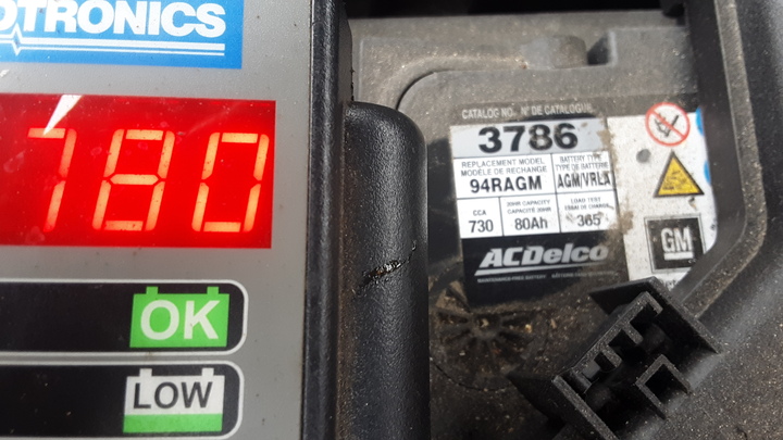
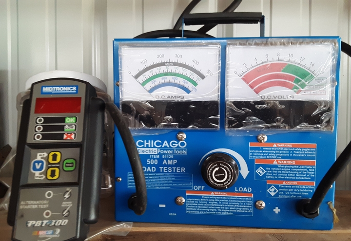
If I could only have one meter to work on tractors I would have a Midtronics.
They are not cheap but they can measure alternator voltage, estimate cranking and tell you when you have a bad cell.


cvphoto158896.jpg


cvphoto158897.jpg


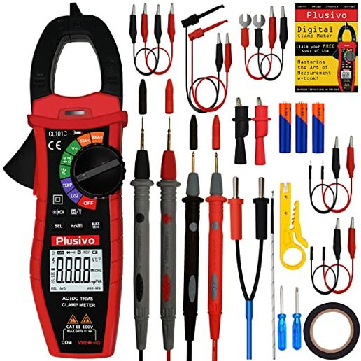
Midtrontics can't measure ohms or DC amps.

So I would also want this meter. It does an excellent job of measuring ohms and DC amps.
I have a precision 1 ohm resistor and the meter shows exactly 1 ohm.
It can measure the DCA of an idiot light bulb, about 0.2 amps. Great meter for finding parasitic loads.

cvphoto158898.jpg
 

We sell tractor parts! We have the parts you need to repair your tractor - the right parts. Our low prices and years of research make us your best choice when you need parts. Shop Online Today.

Back
Top