FE35 timing

triplejim

New User
Part 1
Hoping you can assist me with electronic distributor timing on a FE35 petrol

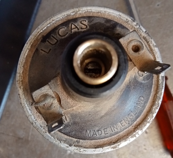
Firstly, had to make a brass insert of the Lucas coil as the new lead wouldnt fit.
Then bought No1 cyclinder to compression, felt by finger
The distributor rotor was pointing at No1
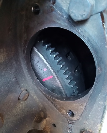
Removed the starter motor, inserted 1/4 dowell so 0 degrees timing mark was set
Then tightened distributor with the rotor centred on the magnetic trigger ring

I was going to use a timing light but tractor has new sleeves, pistons etc and hard to manually crank
So I refitted starter motor, it went first time, adjusted carby a little as plugs were ooty
Previously, carby was set at 1 turn on low and high, now 1.3/4 as per manual
 
Part 2

So how to set 5 degrees BTDC?
1 Remove starter motor, hand crank and timing light, might try again this afternoon
2 Remove starter motor, set flywheel at 5BTDC, mark front pulley so timing light off front of engine
3 Calculate the distance on the distributor base, rotor arm goes anti clockwise
360/5 = 72 increments, diameter of distributor = 44mm, circumference = 138mm/72 = 2mm
Rotate distributor clockwise 2mm
 
Part Three
mvphoto88143.jpg


This post was edited by triplejim on 02/17/2022 at 08:23 pm.
 
Part 5
If I upload more than one pic, I get:
"We are sorry, your post contained one or more words that are restricted due to either YT User Community standards or are common indicators of spamming, cracking, or spambot activity. This was most likely accidental but for obvious reasons, the list of such words cannot be published. Please press back arrow and remove any obvious words or unusual character sequences that would not normally occur in speech."
 
PostPosted: Thu May 16, 2019 7:00 am Post subject: Re: Distributor Timing Reply to specific post Reply with
quote

Sir.

I own and have set the ignition timing (6-volts) on my TEA 20 S# 182991 several times and there are NO visual marks
that can be seen on the flywheel when the STARTER is removed!

There is a 1/4 diam. hole just below the starter flange that I insert a 1/4 rod/drill bit into that lines up with a
1/4 hole drilled in the FWD side if the flywheel. This RIGGING procedure is to take place with the #1 piston
traveling up on the compression stroke.

On my TEA 20 this rigging procedure will lock the # 1 cylinder at TOP DEAD CENTER.I then install the DISTRIBUTOR and
turn the distributor until the POINTS are just on the verge of opening. I call the corresponding distributor contact
point in the distributor cap # 1 and connect the remaining three wires to the spark plugs in the correct firing order.

I recently replaced the clutch and pressure plate in TEA 20 S# 182991 and noticed there is an ARROW stamped on the
peripheral of the flywheel. This arrow lines up with a casting mark on the aft side of # 4 cylinder at the same time
the rigging pin aligns with the hole In the engine and the hole in the flywheel.....yes # 1 TOP DEAD CENTER.

I then marked the engine casing with a METAL marker (with starter removed)and placed a mark on a tooth of the ring
gear lining up with my mark on the engine casting. Each tooth of the flywheel is equal to 2.48 deg. (360/145 teeth). I
placed a mark on ten of the teeth.

I gave the tractor a pull and connected a STROBE light to # 1 spark plug (used a 12 volt battery on a work stand)) and
found that the ignition was not at the desired timing point that I preferred 25 deg. With the throttle set so as the
PTO was running at 525 RPM I turned the distributor housing until the distributor was firing at 25 deg BTDC.

NOW:
Here is a note to know. ENGINE S# SIE to S8995E fitted with Lucas dist. MODEL D3A4 Lucas SERVICE # 40132 has a hole in
the flywheel at 10/100/190 and 280 BTDC number 1 cylinder.

ENGINE S# S8996E onwards fitted with Lucas dist. Model D3A4, Lucas service No. 40146 has a hole in the flywheel at TDC
# 1,as well as 90/180/and 270 deg before TDC. CORRECT LOCATION OF TIMING PIN IS TDC of firing stroke # 1 cylinder.

I did notice that on U-TUBE there is a video of some one checking a TEA 20 igniting timing In the above procedure that
I checked mine. Also in the FERGUSON ARCHIVES TEA20 Back to life a posted picture of a Ferguson WITH timing marks on
the FWD face of the flywheel

Bob..Owner TEA-20,,With the Standard Engine....Assembled in Coventry England
 
As you can see from the pics, I timed using method 2 then marked distributor base
That is, I marked the front pulley using 0 and 5 degrees BTDC off the flywheel
Then made a pointer tool so it matched 5 BDTC ( the pulley is rotated around for the pic)
On the pulley, Green is 5 BTDC, yellow is 0
On the Distributor, Green is 5 BTDC, red is 0

I checked pointer tool and front case bumps using strobe light:
If you aim through the bumps, its at a different angle to the pointer
If you aim at the pointer, its right on the front pulley
But both end up been at the same place.

The reason my red mark on the distributor base is more than 2mm is probably due to my static timing not been right
This is an electronic distributor and the test light method doesnt work, you set the centre position of the rotor arm to the magnetic sensor
Its a good start but not accurate.
 

We sell tractor parts! We have the parts you need to repair your tractor - the right parts. Our low prices and years of research make us your best choice when you need parts. Shop Online Today.

Back
Top