


Ford 2N seems to be getting too much voltage to the coil. It's a 12v system. The moving contact of the points on the plastic/fiber arm "slips" outward toward the end of the arm. It's almost like it's getting hot, melting the plastic/fiber arm allowing the contact to "slip". I assumed the ballast resistor was bad so I replaced it. Installed new points, time and adjusted gap. Tractor ran great for about 10 or 15 minutes. Bogged down, spite, sputtered, died. Same thing happened to points. Any ideas? My new resistor bad? I'm perplexed and need to get this thing running.
You are using an out of date browser. It may not display this or other websites correctly.
You should upgrade or use an alternative browser.
You should upgrade or use an alternative browser.

timcasbolt
Well-known Member
- Location
- Cecil County, MD
bad condensor?(quoted from post at 23:15:28 02/07/23) Ford 2N seems to be getting too much voltage to the coil. It's a 12v system. The moving contact of the points on the plastic/fiber arm "slips" outward toward the end of the arm. It's almost like it's getting hot, melting the plastic/fiber arm allowing the contact to "slip". I assumed the ballast resistor was bad so I replaced it. Installed new points, time and adjusted gap. Tractor ran great for about 10 or 15 minutes. Bogged down, spite, sputtered, died. Same thing happened to points. Any ideas? My new resistor bad? I'm perplexed and need to get this thing running.
Steve@Advance
Well-known Member
For the points to get hot enough to discolor and melt the rub block in 15
minutes, something is seriously wrong. There should be a small amount of
grease on the rub block, but even dry it would not fail that quickly.
For the points to be carrying that much amperage, the coil would also be
getting extremely hot. It should not be noticeably hotter than the
surrounding components. Not much can go wrong with a resistor to cause it
to have less resistance than it is supposed to. Burn open, yes, but go the
other way, no. Do you know the ohm rating of the resistor? Should be
around 1 1/2 ohm.
A few things come to mind, either the coil is shorted internally, the
points are improperly manufactures with the wrong material in the rub
block, or possibly the distributor bearing is seized and the shaft is
getting hot. Did the distributor turn freely when it was off?
Yes it turns freely. I'm not sure what the resistor rating is. I am assuming the ballast resistor would drop the voltage from ~14v to ~10v but it's about the same in and out. I'm buying parts off Amazon, which may be my problem. How can I test the the coil to see if it is shorted internally? I'll check the resistance of the resistor tomorrow to verify 1.5 ohms.
Thanks!

wore out
Well-known Member
(quoted from post at 17:15:28 02/07/23) Ford 2N seems to be getting too much voltage to the coil. It's a 12v system. The moving contact of the points on the plastic/fiber arm "slips" outward toward the end of the arm. It's almost like it's getting hot, melting the plastic/fiber arm allowing the contact to "slip". I assumed the ballast resistor was bad so I replaced it. Installed new points, time and adjusted gap. Tractor ran great for about 10 or 15 minutes. Bogged down, spite, sputtered, died. Same thing happened to points. Any ideas? My new resistor bad? I'm perplexed and need to get this thing running.
What coil are you using in you 12 Volt system?
If an original ''6 Volt'' coil or equivalent the original OEM ballast resistor or equivalent needs to be retained PLUS a ''converting resistor'' typically in the 1.5 - 2 ohms range needs to be added.
If a typical modern 12 Volt aftermarket coil has been installed the original ballast resistor needs to be kept in the circuit as the typical aftermarket ''square'' coils are not ''true'' 12 Volt coils and need to have the OEM or equivalent ballast resistor in the circuit.
Trouble is, most of these parts now come from ''The Land of Almost Right'' and ''equivalent'' parts often aren't.
used red MN
Well-known Member
- Location
- Coon Rapids, MN
Hello Don welcome to YT! I am going to take a real
shot in the dark here. Did you convert this tractor to 12
volts just recently? Did you by chance also install a one
wire alternator of some type? If so where does the wire
that connects to the large post on the back of the
alternator connecting to? My theory is that you have a
one wire alternator, some of them require to be revved
up a fair amount to start charging. So the alternator
output is not connected to the tractor correctly and is
sending too much current to the ignition when it starts
charging.
Second idea is where are you buying the points sets?
They could be extremely elcheapo.
Pictures of what you have going on would be great
here is some info on that for a new poster. At the end
of 2022 the forum host here changed the requirements
to new posters to be able to post photos from a post
count of 5 posts to 1 post. I believe this change was
only made on ..Modern View.. so you need to post from
there. In Modern View you will see the Classic View
option in a red outlined box at the top, just adding this
as a way to verify you are in ..Modern view.. Your
picture should post if you have at least one post if
everything I understood about the change is correct.
This restriction was a way to keep internet bad guys
from dropping in and posting bad pictures with hidden
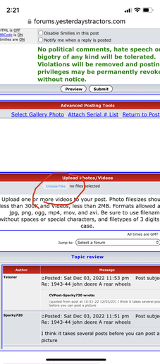
viruses. Pictures post through the ..Choose files..
button or some such name just below where it says
..Upload Photos/Videos.. down lower in the ..New post
and reply windows, see picture. They cannot be pasted
into the text area as a file.
shot in the dark here. Did you convert this tractor to 12
volts just recently? Did you by chance also install a one
wire alternator of some type? If so where does the wire
that connects to the large post on the back of the
alternator connecting to? My theory is that you have a
one wire alternator, some of them require to be revved
up a fair amount to start charging. So the alternator
output is not connected to the tractor correctly and is
sending too much current to the ignition when it starts
charging.
Second idea is where are you buying the points sets?
They could be extremely elcheapo.
Pictures of what you have going on would be great
here is some info on that for a new poster. At the end
of 2022 the forum host here changed the requirements
to new posters to be able to post photos from a post
count of 5 posts to 1 post. I believe this change was
only made on ..Modern View.. so you need to post from
there. In Modern View you will see the Classic View
option in a red outlined box at the top, just adding this
as a way to verify you are in ..Modern view.. Your
picture should post if you have at least one post if
everything I understood about the change is correct.
This restriction was a way to keep internet bad guys
from dropping in and posting bad pictures with hidden
viruses. Pictures post through the ..Choose files..
button or some such name just below where it says
..Upload Photos/Videos.. down lower in the ..New post
and reply windows, see picture. They cannot be pasted
into the text area as a file.
caterpillar guy
Well-known Member
I'm going to say the coil is getting to much juice causing most of your problems or is went bad in a winding inside. Then for the capacitor/condenser all it does is buffer the ark when the points open.
Steve@Advance
Well-known Member
No, a bad condenser would not cause that.
It would shorten the points life, but not that quickly or drastically.
Usually a bad condenser will cause no start or poor performance.
It would shorten the points life, but not that quickly or drastically.
Usually a bad condenser will cause no start or poor performance.

J.Wondergem
Well-known Member
- Location
- Rockford, Mi.
Use a multi meter and see how much juice is coming thru the coil.
Thanks "used red MN" and everyone else helping! Ask your responses are helpful. It was already converted to 12v when I bought it about 4 years ago. It is a1-wire alternator. That wire is connected to the ignition switch which is also tied to one side of the ballast resistor. From the other side of the resistor, a wire goes to the coil. I haven't changed any of the wiring but I have replaced plugs, wires, distributor, points, breaker plate, starter, battery in the past. Since this issue started, I've replaced the distributor, points a few times (because this happens when I start it back up and get it running again) and breaker plate (because I broke one replacing the points), and resistor. I am buying parts off Amazon... that may be my problem.(reply to post at 21:48:13 02/07/23)
used red MN
Well-known Member
- Location
- Coon Rapids, MN
Sorry this is long, but this needs some details to be
able to work through it properly. Well hopefully I get a
little help or nod of approval from some Ford guys that
the information I give here is correct. I am not a Ford
guy never been around them still trying to learn some
of there oddities. The connections of your alternator
output to the ignition switch gets the job done but it
NOT correct. In fact depending on how they wired it
you may even have some melting insulation up under
the dash where too much current was feeding through
wiring. Check the wiring between the ignition switch
and the ammeter that is where too much current
..amps.. may have been passing. Now here is the part I
am still learning on. I am attaching a wiring diagram
that I believe is correct, see 1st link. I am referring to
the second diagram on that page named ..12 Volt
Conversion.. In the upper center it shows a ..terminal
block.. the bottom center terminal of that is the
suggested connection where the Alternator output
wire should go. There is a possibility your tractor was
wires without this. That block is an original part which
is one of the Ford oddities I recently learned about.
This site offers that part, see 2nd link. I say it is an
oddity because very few original 6 volt systems used
resistors but apparently these did and they are said to
be 0.5 ohms. Also another place I am not certain what
correctly applies to the different models but in stock
form I believe your tractor would have a ..front mount 6
volt coil.. If so when converting to 12 volts your ignition
power needs to come from the switch through the .5
ohm resistor on the terminal block and then again in
series through the 1.6 ohm ballast resistor and then to
the coil. All this is shown on the diagram. I also do not
know exactly how that terminal block mounts it
appears that it may be made of an insulating fiber
board and use some counter sunk head screws for
mounting. If you go to the YT parts from the big
..Tractor Parts.. square at the top of the page and
navigate down to the 2N electrical section you will see
there is another more expensive terminal block sold by
them and it shows the mount hardware with it. If you
did not have this block before I said earlier the
alternator is suggested to connect there. I personally
would run the alternator output wire up to the right
side terminal of the ammeter as shown on the diagram.
Defining which terminal is the actual correct one to
connect to on your tractor left..right etc. can be done
by placing it on the ..opposite.. terminal of the one that
is going to battery power. There may be, in fact it is
likely, there will be multiple wires on that terminal.
Without the ..terminal block.. that amp gauge terminal
could be the connection place for the ignition switch
and the light power feed. Doing it this way eliminates
the extra connections made by use of the ..terminal
block.. I know this deviation from the diagram
complicates the finished product but I personally think
it is the best method if you are not looking for
originality, that goes out the window when you change
it to 12 volts. I should add that the alt. output feed wire
to the ammeter should be 10 gauge as should the wire
that connects to the opposite side of the ammeter that
goes to pick up battery power which will be from the
solenoid stud where the positive battery cable
connects. I hope this cures your problem. I also hope
other Ford guys stop by and add any needed
corrections or comments.
Ford wiring diagrams
YT Ford 2N terminal block/resistor
Mine definitely does not have the wiring block. This is great info. I will check my wiring against the diagram. I can't imagine it's Wimmer just because it's been running great since I've had it for more than 4 years until recently. I wonder if I converted it to electronic ignition, if that works solve all my problems? I found this kit... https://www.yesterdaystractors.com/Ford-2N_Electronic-Ignition-Conversion-Kit-12-volt-negative-ground_1247.html
Thoughts?
used red MN
Well-known Member
- Location
- Coon Rapids, MN
I am not sure exactly what you are saying I think the
spell check swapped a word on you ..Wimmers.. is
maybe supposed to be ..wiring? Then I guess that
makes sense. The question I have is do you have an
original 6 volt front mount coil? If so you need to have
an additional 2.1 ohms of resistance in your ignition
circuit. Whether that is by adding the 0.5 ohm stock
resistor along with the 1.6 ohm ballast resistor or find a
2 ohm ballast resistor would probably be close
enough. You say if it was wired improperly how did it
run fine for 4 years? The melting wiring I suggested
could be the answer. If the amperage coming out of
the alternator finds resistance in the wiring it will raise
the voltage. So the alternator being connected to the
ignition switch may very well be increasing the ignition
voltage. If something about the wiring is losing
connection or a wire has over heated over time this
could actually change things. So it may not be able to
work as before even though you made no real changes.
I would not recommend installing an electronic ignition
until you get your problem with a points style ignition
figured out. If you install the EI and start burning out
modules at $100 a piece you will be very unhappy.
Yes that was supposed to be "wiring". I should proof read better. I'm sure the coil I put on it is 12v. However, as I previously stated, I installed a new ballast resistor. Then after ruining another new set of points, I decided "hmmm... this might be a could time to stop assuming and start measuring". With the key on engine off, I'm getting about 1 volt drop across the resistor. With the engine running, I'm getting a little over 14v from battery to resistor and still only about 1v drop. Another bad resistor? When I was shopping for resistors, I can't find values on them... how can I know if I am buying the right one. Obviously I can't trust the one I am buying is the right one just because it says it's for a Ford 2N. So, when I order another one, how can I know it's the correct one? what should the ohm reading be out of the box? What should the voltage drop be with key on engine off? What should the voltage drop be with engine running? What should my voltage be at the coil (i would assume around 9v)? I thought converting to EI because 12-14v would be ok right?

We sell tractor parts! We have the parts you need to repair your tractor - the right parts. Our low prices and years of research make us your best choice when you need parts. Shop Online Today.
Copyright © 1997-2025 Yesterday's Tractor Co.
All Rights Reserved. Reproduction of any part of this website, including design and content, without written permission is strictly prohibited. Trade Marks and Trade Names contained and used in this Website are those of others, and are used in this Website in a descriptive sense to refer to the products of others. Use of this Web site constitutes acceptance of our User Agreement and Privacy Policy TRADEMARK DISCLAIMER: Tradenames and Trademarks referred to within Yesterday's Tractor Co. products and within the Yesterday's Tractor Co. websites are the property of their respective trademark holders. None of these trademark holders are affiliated with Yesterday's Tractor Co., our products, or our website nor are we sponsored by them. John Deere and its logos are the registered trademarks of the John Deere Corporation. Agco, Agco Allis, White, Massey Ferguson and their logos are the registered trademarks of AGCO Corporation. Case, Case-IH, Farmall, International Harvester, New Holland and their logos are registered trademarks of CNH Global N.V.
Yesterday's Tractors - Antique Tractor Headquarters
Website Accessibility Policy