


trying2mow
Member
Please tell me how to wire in an amp meter on my tractor(8N). Do I hook it in series with the pos terminal of battery? If so will I have to put a giant wire in to carry the starter load? Thank you!!
very long time ago, I took an exam and the professor wrote that "you should have stopped before adding that last sentence, which demonstrated that you lacked the understanding that you had shown mastery of up to that poin", which made what otherwise would have been a correct answer into an incorrect answer. Same here, Bill......should have stopped before, " In the 8N charging circuit (positive ground), they followed this accepted practice. Ford wired it into the positive leg of the circuit because the positive leg is at ground potential."(quoted from post at 16:48:14 11/18/16) An ammeter can be inserted into either the positive or the negative leg of a DC circuit because, under Kirchoff's law, the current flowing in any circuit is the same everywhere in the circuit. It just needs to be wired with the opposite polarity when inserted in the negative leg of the circuit, as opposed to the positive leg. In the electronics industry, and in a normal (negative ground) DC circuit, they always install an ammeter in the negative leg because then you don't have to worry about shorting the meter terminals to ground and burning something up, or getting a bad shock when you try to adjust the meter movement. In the 8N charging circuit (positive ground), they followed this accepted practice. Ford wired it into the positive leg of the circuit because the positive leg is at ground potential.
es. On those tractors, about the only way I see to put the ammeter in the grounded (positive side) circuit is to get a really big one, about 200-400amperes, so that it can handle starter current. But one that could read that size current would scarcely indicate 3-4 amps of charging current.(quoted from post at 17:58:39 11/18/16) Oops, JMOR, do you mean that the ammeter is really in the negative side of the circuit? If so, MY BAD!
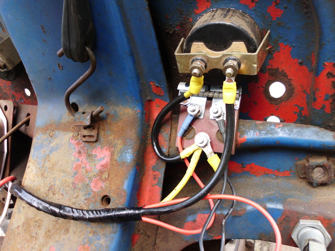
y old 8N was converted to 12V and has a neg ground. My set up looks different than your pic. I do have one long ceramic resistor. I guess I go from solenoid through meter to the resistor but which end? thanx(quoted from post at 11:02:24 11/18/16) On the early 8N the 10-12 gauge wire comes off the solenoid and thru the ammeter to the hot terminal on the resistor. Picture of one I just did using JMOR pictogram as a guide.
I'll echo Bruce's statement. Google JMOR's wiring diagrams.(quoted from post at 00:15:18 11/19/16)y old 8N was converted to 12V and has a neg ground. My set up looks different than your pic. I do have one long ceramic resistor. I guess I go from solenoid through meter to the resistor but which end? thanx(quoted from post at 11:02:24 11/18/16) On the early 8N the 10-12 gauge wire comes off the solenoid and thru the ammeter to the hot terminal on the resistor. Picture of one I just did using JMOR pictogram as a guide.


We sell tractor parts! We have the parts you need to repair your tractor - the right parts. Our low prices and years of research make us your best choice when you need parts. Shop Online Today.
Copyright © 1997-2025 Yesterday's Tractor Co.
All Rights Reserved. Reproduction of any part of this website, including design and content, without written permission is strictly prohibited. Trade Marks and Trade Names contained and used in this Website are those of others, and are used in this Website in a descriptive sense to refer to the products of others. Use of this Web site constitutes acceptance of our User Agreement and Privacy Policy TRADEMARK DISCLAIMER: Tradenames and Trademarks referred to within Yesterday's Tractor Co. products and within the Yesterday's Tractor Co. websites are the property of their respective trademark holders. None of these trademark holders are affiliated with Yesterday's Tractor Co., our products, or our website nor are we sponsored by them. John Deere and its logos are the registered trademarks of the John Deere Corporation. Agco, Agco Allis, White, Massey Ferguson and their logos are the registered trademarks of AGCO Corporation. Case, Case-IH, Farmall, International Harvester, New Holland and their logos are registered trademarks of CNH Global N.V.
Yesterday's Tractors - Antique Tractor Headquarters
Website Accessibility Policy