Regulator wiirring 48 JD A

Elbrus

Member
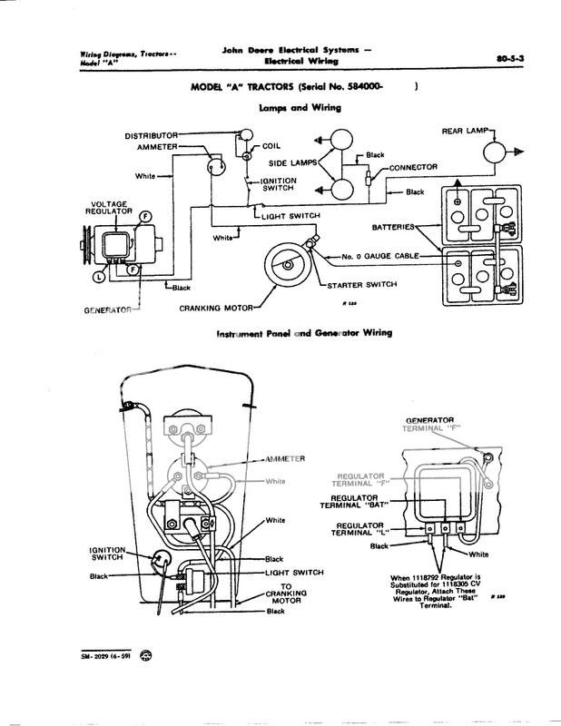
I need help identifying the terminals 1 and 2 on the regulator in the photo. They both appear to be an open or very high resistance to the base. Terminal 3 is aesssentilly a direct contact. terminnal 4 from the underneath has about 24 ohms. Based on the order I belive the wiring should be:
Reg. term. 1 - black wire/lights
Reg. term. 2 = white wire/amp meter/Neg bat.
Reg. term. 3 - Generator Field terminal
Reg. term/wire. 4 - Generator Armature terminal

Can someone verify the correct wiring for terminal 1 and 2?
Thanks in adavance.
a140838.jpg
 
For a 4 terminal (BAT LOAD GEN/ARM & FLD) Voltage Regulator:

BAT will measure near an open (approaches infinity subject to meter) circuit, I.E. VERY HIGH OHMS, to the case/frame.........It wires to the Load (NOT Battery/Starter) side of ammeter.

ARM/GEN is usually underneath or off on one corner all by itself...........It wires to the Gennys ARM post.

LOAD (L)) feeds hot battery voltage to loads such as Lights and Ignition via it wiring to the light/ignition switch input.

FLD will measure low ohms to case frame, it wires to the gennys FLD post.

On many 4 terminal VR's with the three side by side terminals (ARM underneath, depends on manufacturer) BAT is next to LOAD and the third is FLD (SEE DIAGRAM). There's all sorts of vendors now, USA and China plus NOS out there, so there's no way I'm going to guarantee which are which, as I learned NEVER SAY NEVER AND NEVER SAY ALWAYS because Billy Bob or Bubba will crawl out of the woodwork and find one that is different.

HOWEVER the theory above holds true so theres a darn good chance that BAT is the open circuit to case/frame,,,,,,,,,,,,FLD is the one with low ohms to case/frame,,,,,,,,,,,,,,ARM/GEN is the terminal underneath,,,,,,,,,,,And LOAD is the remaining one next to the BAT terminal.....

NOTE: on the Diagram left to right the terminals are LOAD BAT FLD but no way can I guarantee that's true for your VR

DISCLAIMER: This is merely an opinion, and like allllllllllllll other opinions here, regardless if they agree or disagree, may be right and they may be wrong, Im NOT saying one way or the other, take it or leave it at your own peril, NO WARRANTY.

John T
A-3-JPEG.jpg
 
John
Thanks for your reply. I also believe I have it wired correctly. I had read many prior posts and had that diagram. But my major question was in determining the load from the bat terminal on the VR. they both measure about 500 MOhms on a Fluke 335. So I really just used the order in the diagram that you also showed. I ordered the VR a while back from this site, so I hope it is in the shall I say "standard" configuration.
 
Well that"s an idea! I never noticed any markings, then again I didn"t have my glasses either. Thanks for the note. I"ll definitely look.
 
Yesterday's Tractor Forums

We sell tractor parts! We have the parts you need to repair your tractor - the right parts. Our low prices and years of research make us your best choice when you need parts. Shop Online Today.

Back
Top