
I have several tractors that use a resistor on 12 volt conversions and have seen other converted and every one had the resistor before the coil. I saw one today that had the resistor between the coil and the battery ignition. Is that an acceptable way to wire the tractor? Seems like the extra voltage from the coil through the resistor would make the resistor over heat or cut the voltage needed for the plugs. Tractor has ran that way this summer. This is on a Ford 4000 4 cylinder engine.
You are using an out of date browser. It may not display this or other websites correctly.
You should upgrade or use an alternative browser.
You should upgrade or use an alternative browser.
- Thread starter Charlie M
- Start date
wore out
Well-known Member
I have several tractors that use a resistor on 12 volt conversions and have seen other converted and every one had the resistor before the coil. I saw one today that had the resistor between the coil and the battery ignition. Is that an acceptable way to wire the tractor? Seems like the extra voltage from the coil through the resistor would make the resistor over heat or cut the voltage needed for the plugs. Tractor has ran that way this summer. This is on a Ford 4000 4 cylinder engine.
You have witnessed the fact that it "works" the way it is but I've never seen an example of the maker of the tractor or vehicle doing that. either the actual machine or a wiring diagram of such.
Introducing resistance between the condenser and coil MAY affect spark a little during the"'ringing phase" of the spark waveform.
Personally, if I owned it or was hired to work on it the resistor would get moved to the conventional/"correct" part of the circuit.
stevieb49829
Well-known Member
- Location
- Spirit Lake, Idaho
Charlie, normally, a ballast resistor is used between the ignition and the coil to reduce voltage, IF you have converted to a 12V system and retained the 6V coil. This has been covered in-depth over the last few months, so a search will find more information on the resistance to shoot for. Also, people have been known to use a resistor in the "excite" circuit to a 3-wire alternator. I prefer to use a diode in that circuit, so there is no chance of a slow backfeed drain when the tractor sits. So be clear on the terminology you use to describe the situation. I'm still not sure what difference there is in your description of the two methods. Sorry for any overlap, Wore Out got his reply done faster. steveI have several tractors that use a resistor on 12 volt conversions and have seen other converted and every one had the resistor before the coil. I saw one today that had the resistor between the coil and the battery ignition. Is that an acceptable way to wire the tractor? Seems like the extra voltage from the coil through the resistor would make the resistor over heat or cut the voltage needed for the plugs. Tractor has ran that way this summer. This is on a Ford 4000 4 cylinder engine.
Janicholson
Well-known Member
Not a flame If a correct resistor is used in the excite circuit, (like 10ohm 10 watt) the regulator sees that amount of resistance as though similar to a dash light resistance. Dash lights (idiot lights) are also grounded and would provide a path to ground. Three wire alternator regulators "see" that as a usable ground when stopped, and change the #1 terminal to ground. That real ground through the regulator is what causes the idiot light to come on with the key and off when running/charging. JimCharlie, normally, a ballast resistor is used between the ignition and the coil to reduce voltage, IF you have converted to a 12V system and retained the 6V coil. This has been covered in-depth over the last few months, so a search will find more information on the resistance to shoot for. Also, people have been known to use a resistor in the "excite" circuit to a 3-wire alternator. I prefer to use a diode in that circuit, so there is no chance of a slow backfeed drain when the tractor sits. So be clear on the terminology you use to describe the situation. I'm still not sure what difference there is in your description of the two methods. Sorry for any overlap, Wore Out got his reply done faster. steve
Janicholson
Well-known Member
I agree. The coil is electronically operating with the condenser during spark discharge. I think there should be no resistance between them. In a series circuit it would not make a difference, this is an AC electronic interaction. JimYou have witnessed the fact that it "works" the way it is but I've never seen an example of the maker of the tractor or vehicle doing that. either the actual machine or a wiring diagram of such.
Introducing resistance between the condenser and coil MAY affect spark a little during the"'ringing phase" of the spark waveform.
Personally, if I owned it or was hired to work on it the resistor would get moved to the conventional/"correct" part of the circuit.
wore out
Well-known Member
As you know (but some may not), to add to the confusion, some machines used a10 Ohm ceramic resistor in the alternator/VR circuit with the exact same physical appearance of a 1.5 or 1.75 (etc.) primary resistor, IH for one.Not a flame If a correct resistor is used in the excite circuit, (like 10ohm 10 watt) the regulator sees that amount of resistance as though similar to a dash light resistance. Dash lights (idiot lights) are also grounded and would provide a path to ground. Three wire alternator regulators "see" that as a usable ground when stopped, and change the #1 terminal to ground. That real ground through the regulator is what causes the idiot light to come on with the key and off when running/charging. Jim
used red MN
Well-known Member
- Location
- Coon Rapids, MN
I can only assume that what Charlie meant and based on woreout’s explanations in his reply that is what was meant, (how it is configured) is the resistor is between the coil and “distributor”. I believe this comes from terminology that A. You can have a “Magneto Ignition” so B. The alternative is “Battery Ignition” to me distributor would have been a more clear description.Charlie, normally, a ballast resistor is used between the ignition and the coil to reduce voltage, IF you have converted to a 12V system and retained the 6V coil. This has been covered in-depth over the last few months, so a search will find more information on the resistance to shoot for. Also, people have been known to use a resistor in the "excite" circuit to a 3-wire alternator. I prefer to use a diode in that circuit, so there is no chance of a slow backfeed drain when the tractor sits. So be clear on the terminology you use to describe the situation. I'm still not sure what difference there is in your description of the two methods. Sorry for any overlap, Wore Out got his reply done faster. steve
I helped one gentleman that showed he had his resistor located off his ammeter this was an 8N that has the goofy terminal block and resistor behind the dash. Luckily he followed a diagram that connected his alternator output direct to the solenoid. So his power ran through that extra resistor and over to the ignition switch. Had he powered lights or something else the load would have went thorough that resistor and burnt it out. With only the ignition being powered by the resistor it worked fine. Since it ran this way for some amount of time it took a fair bit of convincing to get him to accept it needed to be changed. The general population can certainly create some wiring foo-baas.
Last edited:
Even if it still can "work" in either place I suggest the ballast be wired between the ign switch output and the coils input NOT between the coils output and points/condensor. With the points (in parallel with condensor) opening and closing theres some interaction with the coil and condensor and I prefer there be no added resistance in that circuit. Im talking about an ignition circuit coil and ballast here NOT in the charging system...
John T
John T
rvirgil_KS
Well-known Member
"I prefer to use a diode in that circuit, so there is no chance of a slow backfeed drain when the tractor sits." One side of the resistor, diode, or charge light goes to the ignition switch. When the switch is off there should be no source for backfeed.Charlie, normally, a ballast resistor is used between the ignition and the coil to reduce voltage, IF you have converted to a 12V system and retained the 6V coil. This has been covered in-depth over the last few months, so a search will find more information on the resistance to shoot for. Also, people have been known to use a resistor in the "excite" circuit to a 3-wire alternator. I prefer to use a diode in that circuit, so there is no chance of a slow backfeed drain when the tractor sits. So be clear on the terminology you use to describe the situation. I'm still not sure what difference there is in your description of the two methods. Sorry for any overlap, Wore Out got his reply done faster. steve
Janicholson
Well-known Member
I understand what you are saying. The back feed is through the coil primary to the connection to the points, and then ground, as most often the points are closed when the tractor stops. However, the 10 ohm resistor/light/or diode provide enough resistance in that circuit to cause the internal regulator to change the #1 terminal to an apparent ground. thus no back feed or drain happens. Jim"I prefer to use a diode in that circuit, so there is no chance of a slow backfeed drain when the tractor sits." One side of the resistor, diode, or charge light goes to the ignition switch. When the switch is off there should be no source for backfeed.
Tim PloughNman Daley RIP
Well-known Member
I have several tractors that use a resistor on 12 volt conversions and have seen other converted and every one had the resistor before the coil. I saw one today that had the resistor between the coil and the battery ignition. Is that an acceptable way to wire the tractor? Seems like the extra voltage from the coil through the resistor would make the resistor over heat or cut the voltage needed for the plugs. Tractor has ran that way this summer. This is on a Ford 4000 4 cylinder engine.ard n a
When I wrote this I remember a fire storm last year concerning using the term distributor vs battery ignition vs magneto so not wanting to stir up that bee nest again I wrote it the way I did. Yes the resistor is located between the coil and the distributor.I can only assume that what Charlie meant and based on woreout’s explanations in his reply that is what was meant, (how it is configured) is the resistor is between the coil and “distributor”. I believe this comes from terminology that A. You can have a “Magneto Ignition” so B. The alternative is “Battery Ignition” to me distributor would have been a more clear description.
I helped one gentleman that showed he had his resistor located off his ammeter this was an 8N that has the goofy terminal block and resistor behind the dash. Luckily he followed a diagram that connected his alternator output direct to the solenoid. So his power ran through that extra resistor and over to the ignition switch. Had he powered lights or something else the load would have went thorough that resistor and burnt it out. With only the ignition being powered by the resistor it worked fine. Since it ran this way for some amount of time it took a fair bit of convincing to get him to accept it needed to be changed. The general population can certainly create some wiring foo-baas.
Tim PloughNman Daley RIP
Well-known Member
I have several tractors that use a resistor on 12 volt conversions and have seen other converted and every one had the resistor before the coil. I saw one today that had the resistor between the coil and the battery ignition. Is that an acceptable way to wire the tractor? Seems like the extra voltage from the coil through the resistor would make the resistor over heat or cut the voltage needed for the plugs. Tractor has ran that way this summer. This is on a Ford 4000 4 cylinder engine.
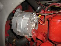
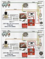
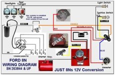
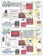
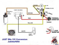
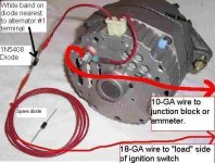
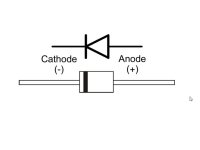
On a FORD 12V Conversion, the GEN and VR are removed from the circuit altogether to begin with. Many think you keep the VR but, NO, discard it. If you keep your OEM 6V COIL you will need to add an external 1.5 OHM Resistor or Diode to the circuit -SEE PIX. DIODES are polarity sensitive and have a band markling on end as shown. If you swap out the 6V COIL for a verified 12V COIL you DO NOT ADD THE EXTRA Resistor. ALSO, some confuse the OEM Ballast Resistor that is only used early N's with the front mount distributor as I being used on all circuits. Wrong. The OEM Ballast Resistor is required on both the 6V and the 12V setups with a front mount. After 1950 with advent of the side mount dist this resistor was eliminated. I advise to swap out your 6V Coil for a 12V coil to avoid any extra parts and wires dangling around. The DELCO 10-SI 1-WIRE ALTERNATOR is as proven performer and there is also a 3-WIRE Unit that will work as well. Whichever you use, a GEN or an ALT, be sure it has a fan belt tensioning bracket attached to keep proper belt tension set. Without it you will never charge the battery and also a loose or improper belt will affect the cooling system as well and possibly to the water pump. OEM 6V GEN came with a belt tensioner. ALT kits are not all equal and may or may not include one - check you supplier when buying.
Tim Daley (MI)
Attachments
-
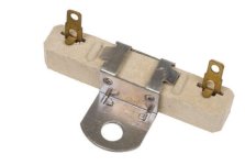 1.5 OHM CERAMIC RESISTOR.jpg14.8 KB · Views: 11
 -
 3-WIRE ALT CONFIG.jpg101.7 KB · Views: 12
 -
 8N 12V & 1-WIRE ALT.jpg1.6 MB · Views: 11
 -
 8N 12V WIRING OPTION.jpg59.1 KB · Views: 13
 -
 8N WIRING DIAGRAMS.jpg182.8 KB · Views: 11
 -
 12V CONVERSION USING 12V COIL.jpg100.1 KB · Views: 14
 -
 DELCO 10-SI 3-WIRE ALTERNATOR.jpg39.9 KB · Views: 11
 -
 DIODE.jpg17.1 KB · Views: 10
used red MN
Well-known Member
- Location
- Coon Rapids, MN
“Fire storms” are the norm here!When I wrote this I remember a fire storm last year concerning using the term distributor vs battery ignition vs magneto so not wanting to stir up that bee nest again I wrote it the way I did. Yes the resistor is located between the coil and the distributor.
") To many guys here that are convinced they are the only one that could possibly answer something correctly. Plus it keeps their heart rates up promoting good circulation!
To many guys here that are convinced they are the only one that could possibly answer something correctly. Plus it keeps their heart rates up promoting good circulation!Similar threads
We sell tractor parts! We have the parts you need to repair your tractor - the right parts. Our low prices and years of research make us your best choice when you need parts. Shop Online Today.
Copyright © 1997-2024 Yesterday's Tractor Co.
All Rights Reserved. Reproduction of any part of this website, including design and content, without written permission is strictly prohibited. Trade Marks and Trade Names contained and used in this Website are those of others, and are used in this Website in a descriptive sense to refer to the products of others. Use of this Web site constitutes acceptance of our User Agreement and Privacy Policy TRADEMARK DISCLAIMER: Tradenames and Trademarks referred to within Yesterday's Tractor Co. products and within the Yesterday's Tractor Co. websites are the property of their respective trademark holders. None of these trademark holders are affiliated with Yesterday's Tractor Co., our products, or our website nor are we sponsored by them. John Deere and its logos are the registered trademarks of the John Deere Corporation. Agco, Agco Allis, White, Massey Ferguson and their logos are the registered trademarks of AGCO Corporation. Case, Case-IH, Farmall, International Harvester, New Holland and their logos are registered trademarks of CNH Global N.V.
Yesterday's Tractors - Antique Tractor Headquarters
Website Accessibility Policy