574 diesel injector pump timing

I picked up a 574 at an auction recently. I inherited a 574 from my daddy when he passed away but the motor was seized up. The one I bought was running good but he had taken the injector pump off to have it rebuilt. So I took the one off my daddy's and put on this one. I've had the tractor running since the swap. The timing seems off to me. The 4 indentation marks on the back side of the crankshaft pulley. 3 indentations are side by side then the 4th Indentations has a larger spaces between it then ther others. Are these marks to help me find TDC? I'm still a work in progress when it comes to mechanic'n. But I'm enjoying the learning process and determined to figure it out. Any advice would be greatly appreciated and Thank You In Advance
 
A 574 that is set up if no water in the crank case would be a pretty easy fix since it has wet sleeves could just push them out with the piston then press the sleeve off the piston after soaking in some diesel fuel for awhile and might even come loose that way. Or pour some down the injector hole. As for the timing I can llok at that when I get to dad's in the service book on it.
 
The IH Neuss engines are not timed at TDC, but in the 14-18 degrees BTDC range. Clean the pulley well and you will see the timing marks. Align the pump internal mark first, then check the front pulley mark as pump turns 1/2 engine speed.
 
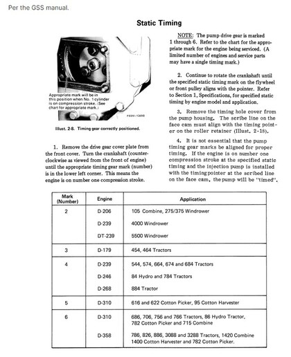
Here is a page from my IH Service Manual that shows injection pump static timing marks.

Hope this helps.


cvphoto137379.jpg
 
(quoted from post at 20:40:50 10/05/22) A 574 that is set up if no water in the crank case would be a pretty easy fix since it has wet sleeves could just push them out with the piston then press the sleeve off the piston after soaking in some diesel fuel for awhile and might even come loose that way. Or pour some down the injector hole. As for the timing I can llok at that when I get to dad's in the service book on it.
 
JimB2 Thank You! These illustrations should help out alot.
I'll definitely use them this evening after work. The IP that was on the tractor originally where the fuel lines connect to the pump the fittings come out straight the IP I switched to the fittings are angled.... I've been told that makes a difference. As long as the timings right it shouldn't matter right?
Thanks Again
 
You are welcome.
Note: Dieseltech is the expert.

Re model of Bosch injection pumps for D239 German Neuss engines

From CIHTECH said, Bosch VA models:
There were 3 different injections pumps used on D239 engines,
Older IH 574, 674, with D239 have either
Bosch Model VA BR lines angled out of head where injections lines attach, over flow valve in the top return banjo bolt.
The over flow valve is an orifice type built into banjo bolt (think really small hole) when installed at incorrect location pump supply you can hardly get any fuel into injection pump
Newer IH 574, 674 and 684 has
Bosch Model VA CR lines came straight out of head, over flow valve built into pump and a standard banjo bolt (same as supply) for return connection.

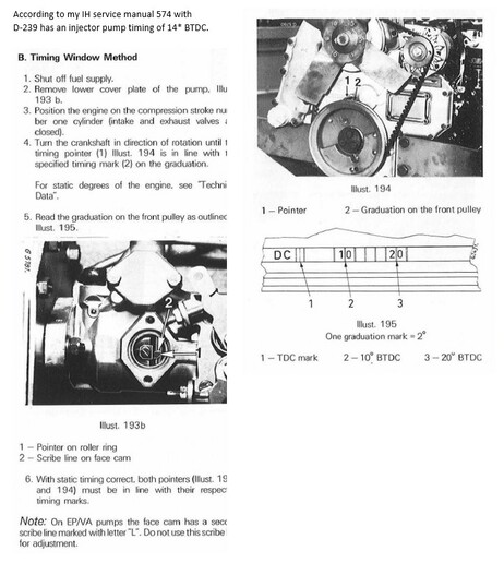
My IH Service Manual says for both Bosch VA models BR and CR the timing is 14* BTDC on gear transmission tractor.

Newer CIH D239 engines in 685, 695 and 4210 have,
Bosch model VE has throttle linkage on top cover, used after serial 18001
 
JImB2... I got engine set at 14 degrees BTDC and turn the pump until the keyway lined up. Doesn't seem to be getting fuel up to the injectors. Before I did theses settings I could get the tractor to start right up but the off start run lever had to be in the off position. Any advice you could give me would be greatly appreciated!
 
Hi, the pump could be timed 180* out because the 14* TDC on the crank pulley will align with the pointer both on the compression stroke and the exhaust stroke.
There is no easy way on a Diesel engine to tell if you are on the compression or exhaust stroke without pulling an injector on #1 cylinder or removing the valve cover and looking at which valves are closed.
That is the reason that it is very important that before removing a pump the timing marks are aligned properly.

You have two options, scribe marks on the pump drive hub and the drive gear, remove the three bolts in the drive hub and turn the drive hub one revolution in the direction of pump travel until the scribe marks align
and re-install bolts OR follow the procedure in the attached photo, for your 574 you will be looking for the #4 on the bottom left corn on the timing gear.
If I recall correctly when pump is timed properly the keyway in the pump drive shaft will be about in the 11 O'clock position although I can't find my note on that.

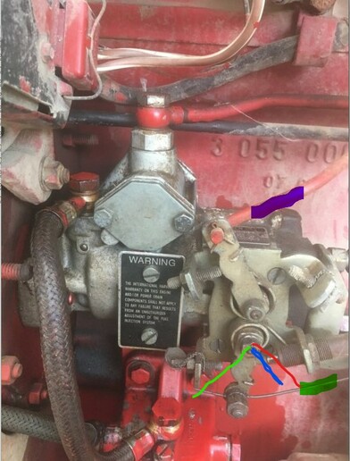
Are you aware of the positions on the STOP/START/RUN lever? See photo of Bosch VA pump, the STOP/START/RUN cable has to be adjusted so in the STOP position the fuel control lever is in the RED line position, for Cold
STARTs or starting engine after bleeding fuel lines, the START position is the BLUE line with the lever just touching the end of the extended plunger, RUN is the GREEN line and lever is fully forward touching the
adjustment screw.

A D-239 can be a bit of a PITA to bleed and get started after any kind of loss of fuel from the lines or filter changes or opening the window on the fuel pump.
Hints:
1) Make sure there is about 3/4 of a tank of Diesel fuel in the tank as these tractors have no inline fuel pump and rely on gravity feed.
You can use a clean rag and an air gun to slightly pressurize the fuel tank.
2) Open bleed screws at top of primary fuel filter and let fuel flow until air bubble free, repeat for secondary fuel filter.
3) With STOP/START/RUN lever in START position attempt to start engine, NEVER CRANK THE STARTER FOR TOO LONG at a time or it will overheat, let it cool between attempts.
4) If #3 fails to start then loosen two injector lines at the rear of the pump and crank engine until fuel dribbles out, then tighten the lines and see if it will start.



cvphoto137479.jpg


cvphoto137480.jpg
 
Hi, I forgot to mention the COLD START throttle settings are different between Bosch VA-BR and VA-CR pumps.

Cold START from IH 454-474-574-674 Operator's Manual
Bosch VA-BR pump(Angled injector ports) - STOP/START/RUN Lever START position and throttle at low idle position
Bosch VA-CR pump(Straight injector ports) - STOP/START/RUN Lever START position and throttle at high idle position

Good luck
 
Jim2 I appreciate you taking the time to send me photos your knowledge.
It's still fires right up with it in the off position then soon as I move it up the least bit it shuts off. That's the way I have to shut it off.
I've got a friend coming by later to help me out and give me a extra set of hands and eyes. Thinking we will remove the valve cover then find the 4 on the gear by the pump. Is the #1 cylinder(firing order) the one closest to the steering wheel? Thanks again

This post was edited by CountryBoy4Life on 10/09/2022 at 09:59 am.
 
Hi, see link below, you can download for free all the European manuals for the IH 454-474-574-674 series tractors from the link below, you do not have to be a member of Redpower.
You may have a made in USA 574 but all that means is the engine and power train were shipped from IH plant in Doncaster, UK in a crate and finally assembly was done in IH Louisville, KY plant with USA made
wheels, Delco electrics, power steering and hydraulic components from IH USA built 404/504 series tractor.

Front of engine, #1 cylinder is closest to the rad.

Re injection pump, I hope someone didn't remove the fuel control lever of the side off the pump and put it back on out of time. There is a procedure in one of the manuals to adjusted the plunger mechanism on
the pump for proper operation but if this pump was working before it maybe so far out of time the engine will only run on the START position. My brother did that on his IH 454 3cyl D-179 when he changed the
front lip seal on the injection pump drive shaft and he removed the three bolts on the drive hub without scribing a mark.
UK IH 574 Manuals
 
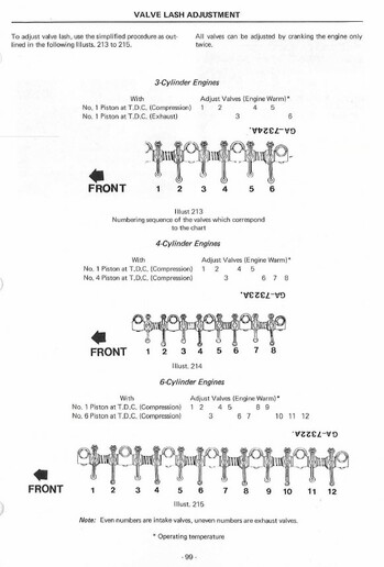
See attached photo to Determine from valve lash adjustment when #1 cyl is on TDC Compression or when #4 cyl is at TDC Compression.
When #1 is TDC Compression both valves will be closed an tappets #1-2 and 4-5 are loose.

cvphoto137642.jpg
 
Dear,
Just same problem. Can anyone help?
IH 674 Mfg Great Britain. 4 cylinder engine, injection pump VA. 1976.

I removed pump but reason not so familiar... I does not mark. Tractor not start. I am not sure, but maybe it "180 degree" problem.

I read service manual, but it not help. Problem is: Cranksaft pulley rotate 720 degree. So 2 turn. TDC mark found in both turn.

So. Pump is now in my hand. I turn it pump saft. Ok. Now it mark INSIDE pump is on line. Just as here is photo opened pump. (JIMB2 here.) Ok, now my pump is adjusted just as it must be.

Then I rotate cranksaft pulley 14 degree BTDC. And then fit the pump.

Ok. Now pump is installed just as it must. Or 180 degree timing error.

---

I opened valve cover. I try read this valve chart. Ok. Now I start rotate it cranksaft pulley. ....cylinder 1 inlet valve start open and is open.... then it close.... then I see cylider 1 exhaust valve start open.... Ok. Inlet valve cylinder 1 is close. Exhaust valve cylinder 1 is close. Clear, now Cylinder 1 is in compression state. I see I am quite near TDC, it TDC mark on pulley tell me, "cylinder 1 is really in TDC". And it adjust value is 14 degree BTDC.

So. Is this my logic really right?
1. Pump adjusted to mark. (From front it looks 11 o clock.) Pump installed, but plate removed. So Pump is in right position. And no turn reason it plate removed.
2. I start rotate cranksaft pulley. I follow valves. Ok. Now I see cylinder #1 both valves are closed. And pulley mark show TDC.
3. Now I turn pulley a little bit. Now found it 14 degree.
4. Now I can install it plate and tighten it.

Is this right? Pulley mark show 14 degree BTDC. Pump mark in line. Cylinder 1 both valves closed. Right?
 
So. Is this my logic really right?
1. Pump adjusted to mark. (From front it looks 11 o clock.) Pump installed, but plate removed. So Pump is in right position. And no turn reason it plate removed.
2. I start rotate cranksaft pulley. I follow valves. Ok. Now I see cylinder #1 both valves are closed. And pulley mark show TDC.
3. Now I turn pulley a little bit. Now found it 14 degree.
4. Now I can install it plate and tighten it.

Is this right? Pulley mark show 14 degree BTDC. Pump mark in line. Cylinder 1 both valves closed. Right?
Everything you did appears to be good except are you sure that you are turning crankshaft in correct direction as the 14* mark should appear before TDC, bump the starter and see the correct rotation of the engine. You want to set the 14* on the correct directional rotation of the crank pulley as there maybe some gear lash between directions. The other thing to look for is on your 574, look for the #4 on the bottom left corn on the large timing gear that drives the pump gear when the pump drive gear keyway is at 11 O'clock.
You do not have to re-install the cover for a quick test, just don't rev the engine above idle.
 
Dear,

Ok, now I found just "how it really work". In nutcell: "When cylinder #4 change from exhaust to in, cylinder #1 is in work phase". Now I really understand it. Simply rotate motor to right rotation. When #4 valves "change", pulley wheel TDC mark tell #1 is tdc, end of compression, fuel injection (14 degree before of course). And pump mark on position. NOW it is clear and simple!

BUT all is not! (Sorry, texts are finnish, I forget save edit version).

* As you see, between TDC mark and needle ("osoitin") are not near together. "Needle" is attached with two bolt. So it location is "exact". BUT. Needle is near "inner" edge and marks are "outer" edge. Maybe right read position is "from front". But I really I does not want remove cooler, front loader etc etc. I can peek it needle only from a little hole under charger. So- how I can read this? Depend of viewing location... it make about 01 degree error in reading... reason distance between mark and needle is about 50 mm.
* As all stupid persons, I marked nothing. Also injection pump. I open it pump lid and I found it pump timing mark. But I remove it "pump indicator needle"- and when I install it back, I notice it is possible move +/- 2 mm. Of course this make error to timing. Only way is remove pump (again!) and carry it to diesel service- only reason adjust it pointer...?

As you see, timing adjust is not easy. First this pulley mark is not exact. Second, I does not understand it "pump indicator needle" location is adjustable...

View attachment neula.jpg
YLEISKUVAT.jpg
 
Yesterday's Tractor Forums

We sell tractor parts! We have the parts you need to repair your tractor - the right parts. Our low prices and years of research make us your best choice when you need parts. Shop Online Today.

Back
Top