Calling a machinist (or 2)

stevieb49829

Well-known Member
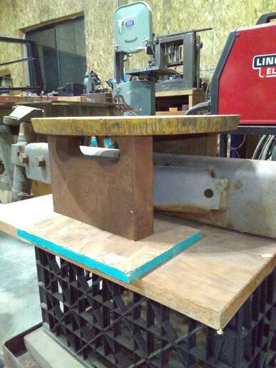
I'm building a front bolster to mount a wide front on my tractor. It will be two chunks of 1-1/2 inch steel, welded vertically about 6 inches apart, to a 3/4 inch mount plate. The chunks will have two holes for the axle pivot pin (actually for the pin bushings). I can rough cut the 2 bushing holes. What do I use, or find someone, to align bore these two holes, finished to the pressed-in bushings? I'm afraid if I get them machined to the press-in dimensions ahead of time, the alignment will not be spot-on when I weld these heavy pieces together. Any technical info is much appreciated. steve
 

Already have the finished axle?
If yes I would use it sandwiched between the bushed plates your having made along with the pivot pin all assembled as if in use.
Then weld the the bushed plates to the 3/4 plate.

I am baffled by the bushed plates being welded vertically to the 3/4 plate though.
 
Maybe I need to explain better: Round 3/4 mount plate that bolts UP to the bottom of the front frame, where the narrow front pedestal bolted before. Just like you suggest, the two heavy plates (welded to the bottom of the mount plate) carry the bushings for the horizontal pivot pin, and the pin passes through those plates and the axle (silver in the pic). In the photo, the 2 inch holes aren't drilled, but you can just barely see the lines drawn for the front one. The big slot at the top is for the steering arm, which may or may not stay there (I'm working on the power steering geometry yet).
cvphoto137408.jpg


If I can't figure out a way to line bore both, once it's welded up, I will follow your suggestion and assemble it all, and carefully weld it up. I've done something like that before, and had to beat the crap out of it to disassemble it, because the weld pulled it in weird directions.
 

I suspect the machine shop might want it all finish welded before the put any pivot shaft holes in the plates. Then honed for the bushings.
That way the holes are for sure in line even if the plates are not perfectly square, parallel, perpendicular to the base plate.???

Might have to really bevel those bushing plates for a good weld.
 
Double, the bevels for deep welds is in the plan. I'm planning on bandsawing at least a 1/2 inch triangle off all weld edges before I start, so there's only 1/2 inch of unwelded area anywhere. Good welds will not be a problem (BTDT for 55+ years). I've just never been able to calculate or compensate for the movement caused by weld contraction during cooling.
 
(quoted from post at 15:07:09 10/06/22) Double, the bevels for deep welds is in the plan. I'm planning on bandsawing at least a 1/2 inch triangle off all weld edges before I start, so there's only 1/2 inch of unwelded area anywhere. Good welds will not be a problem (BTDT for 55+ years). I've just never been able to calculate or compensate for the movement caused by weld contraction during cooling.

Don't feel bad about it. There is no way to eliminate distortion. It's part of welding. Heroes can talk all they want about weld sequencing, workpiece clamping, etc..............................

Metal moves when it's heated/welded.

Get yourself a really large heating tip for your cutting rig. Not a weedburner, but a real heating tip. Something in the 500,000BTU range. Then learn to do heat shrinking (aka flame straightening). I'm not saying you aren't familiar with straightening, but most folks aren't.

Acetylene has a limited draw rate, so you'll have to run your tip on Propane. There's 2 types of tips out there. Rosebud style, which puts out a wider heat cone...........and Spot Heating style, which puts out a very tight cone. Your fuel gas runs at around 30psi, and your O2 runs at about 65psi. So be prepared to go through a few bottles of Oxygen LOL.

And buy some kind of ear protection............these suckers sound like a jet engine when running LOL

This post was edited by farmersamm on 10/08/2022 at 04:33 am.
 
Are you saying I need to pre-heat the whole assembly and then weld it while hot? I have a wood boiler that I can fit it inside, and it could be red-hot after about 20 minutes. Assuming I don't burn all the flesh off my hands and arms, I can set it up to weld when it is really hot. I'd tack it together with a few corner welds first. Sounds like I need to dig the leathers out. Is heat shrinking an art form? I've done it successfully on sheet metal body parts, but not on massive assemblies like this. Thanks for the info, and the encouragement. steve
 
(quoted from post at 11:27:34 10/08/22) Are you saying I need to pre-heat the whole assembly and then weld it while hot? I have a wood boiler that I can fit it inside, and it could be red-hot after about 20 minutes. Assuming I don't burn all the flesh off my hands and arms, I can set it up to weld when it is really hot. I'd tack it together with a few corner welds first. Sounds like I need to dig the leathers out. Is heat shrinking an art form? I've done it successfully on sheet metal body parts, but not on massive assemblies like this. Thanks for the info, and the encouragement. steve

A preheat is around 400*, which can help, but not eliminate the distortion. I don't believe I'd bother.

Try to do identical welds on both sides of a joint as you go. Weld one side, then immediately weld the other side. This will help equalize the stresses. It's like distortion v. distortion.

See what happens (using a double bevel), then you can go from there. Your bevel should look like an arrow pointing at the top piece. Don't single bevel it. Double bevel will give a full penetration weld. Leave enough of a land to locate the pieces........about 1/8" unbeveled at the point of the arrow.

Once you start welding, keep at it to keep the interpass temperature up.

It might turn out near perfect. If you can, use 7018...it's a bit more ductile, and behaves better as the weld cools.
 
OR: I could fabricate a stout jig to keep the parts solidly aligned, weld the parts completely, and heat the assembly in my boiler to relieve the stresses before removing the jig? This is beginning to become a valuable learning experience.
 
I just bought the 7018, but I wasn't planning on making the bevels that deep. I'll do it, though. The metal bandsaw is my friend!! And the one side, then the other, while its still hot, makes a lot of sense. Then if it doesn't stay square and straight, I can beat the crap out of it after I heat it up in my boiler, or get a machine shop to align bore it again. Thanks, again for all your help and expertise. steve
 
You have a few choices as to how you go about it. I like a full penetration weld, but sometimes it's not necessary. It depends on how you intend to load the piece.

I took some pics of pertinent pages in a very good book that should be on the shelf of anybody doing one-offs (IMHO)

mvphoto98169.jpg


mvphoto98170.jpg


This page includes the picture of the fillet tee joint. It's only included so you can read the text, and see the figure it references.

mvphoto98171.jpg


A general table referring to fillet size for given size of plate. Fillet size is measured by the length of the legs.

mvphoto98172.jpg


Sorry about the quality, but the book can't be placed on the scanner bed. I tried to upload these in a larger size, but the forum software compressed them. I hope you can read the small print.

Distill it, and you're either looking at the double bevel, or fairly large fillet welds. Fillets require no grinding though, but they do generate a lot of stress as they're cooling.
 
I'm going on a search for that book. I like it. It looks like a good hardback, by a good company, so it may be readily available. I'm in no hurry to do this right now, so I have the time to do the research. Thank you so much for your help. When I get this done I'll post the results. Steve
 
(quoted from post at 14:41:28 10/10/22) Better drill the holes first. Welding steel hardens it to where the steel is harder than the drill bit.

If the plate is mild steel, as I suspect it is...........it doesn't contain enough carbon to harden with the application of heat. This is why you can weld low carbon mild steel.

To attempt to harden mild steel, you need to carbon soak it, and at best, it might surface harden to a very limited depth.

A36, structural steel, and 1018, are easily welded because they contain about .25% carbon, depending on the specs you read.

The mild steels also contain relatively little sulfur. Sulfur can wreak havoc when attempting to weld.

For those interested............info is widely available on the internet, from suppliers, and other reliable sources. What you want do, is look at either "weldability", "welding procedure", or in the case of machining "machinability".

One of the best open sources for data on steel composition, and properties, is https://www.makeitfrom.com/

One thing related to hardening though............ When you plasma cut mild steel, the area will be Nitrided, causing you to dull HSS cutting tools. This can be avoided by using carbide tools. The nitriding is such a thin layer that you can get under it, but it will ruin a tool.
 
Even on the edge of a torch cut, the mild steel is hard enough to dull a bandsaw blade as it starts a cut through that hardened layer. If I'm not being lazy, I'll do the first 1/8 inch with a cutoff wheel in the 4.5 grinder.
 
I think you may be overthinking the pivot bushing machining a bit. This is simple axle pivot bushings, not engine crankshaft bearings. It's rocking what, 30 degrees total at very low speed. Aerospace perfection is not required.

Any shop with a mill should be able to bore the through hole with sufficient accuracy drilling and then boring with a boring head to size. A Bridgeport type mill could do it in two setups, a machinists level and a coax indicator would keep the setups aligned sufficiently for the application.

WP
 
Thank you for that dose of reality. I was leaning the way of 'what the heck does it matter'. As long as the pin isn't in so much of a bind it instantly takes out the bushings, it should be good to go. But, this project WILL teach me a few more things about welding and distortion. Thanks again for your common sense. steve
 
If you can, have it line bored. You have two separated points that have to be aligned to make it all work. Line boring is the most accurate way to assure this.

I'm currently fighting a setup where it's impossible to line bore the pivots. Unless I'm spot on, it ain't gonna line up. I'm anticipating some disappointment tomorrow when I start the fitup for welding. If I'm off by a few thou, the pivots won't line up.

When two points are separated by a meaningful distance.......let's say a coupla feet......any deviation in the machining on either point, will make for a no go situation.

Being as your work is "new work", not trying to fix something that you don't have drawings for, or known reference points, it might be fine to do it with plain measurements. This assumes all plates are square to each other, and parallel.

I'm not good at math, but think of the deviation caused by .002 over a distance of even a foot. It's a geometry solution. That .002 as it forms an angle from true alignment, will magnify the error by every inch the pivot pin extends from the first bore to the second.

Save some heartache, have it line bored. IMHO of course.

Here's a fella that does a nice job. I didn't see all the parts of the job, but I did see the end result. https://youtu.be/O1pjfO0KYDs

Even the most humble piece of machinery is a wonder of engineering, drafting, jig making, and accurate machine work. The level of precision, unless it's the hinges for your pasture gate, is absolutely astounding.
 
(quoted from post at 21:46:16 10/12/22) Thank you for that dose of reality. I was leaning the way of 'what the heck does it matter'. As long as the pin isn't in so much of a bind it instantly takes out the bushings, it should be good to go. But, this project WILL teach me a few more things about welding and distortion. Thanks again for your common sense. steve

To be clear, I'm suggesting boring it on a mill in two setups *after* welding so that whatever distortion is introduced in the welding is not a factor.

Setup the part on an angle plate in the mill and use a machinists level to get the bushing flange at the top level. Drill and bore the hole in that flange.

Flip the part so the other flange is at the top and again use the machinists level to set the original flange, now at the bottom level. Drill and partially bore the hole in the top flange for access.

Use a coax indicator to reach through to the bottom flange hole and indicate it coaxial to the spindle and also use the coax indicator to check at the bottom edge of that hole as well as the top edge to fine tune the hole to be parallel to the spindle axis before finish boring the hole in the top flange.

This should have it well within reasonable tolerance for the application. If you have a sufficiently long tool bit for the boring head to reach to the bottom you could bore both flanges in a single setup.
 
"To be clear, I'm suggesting boring it on a mill in two setups *after* welding so that whatever distortion is introduced in the welding is not a factor."

x2
 

We sell tractor parts! We have the parts you need to repair your tractor - the right parts. Our low prices and years of research make us your best choice when you need parts. Shop Online Today.

Back
Top