I am getting rained out, looks like the rest of the day isn't going to get any better.
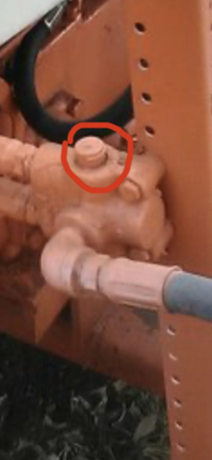
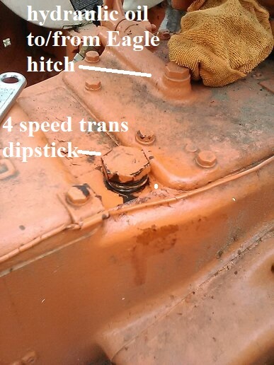
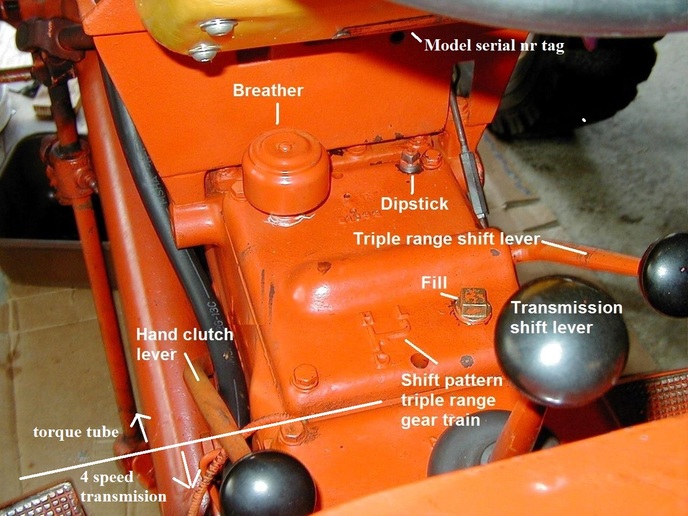
we need to get the tractor assembly I.D. a little better. That is the dipstick for the 4
speed transmission and final drive. Factory oil was about 4 gal SAE 90 gear oil. The The
notch near the bottom of the dipstick is the full mark. The drain plug is under near the
rear axle off-set to the right side.
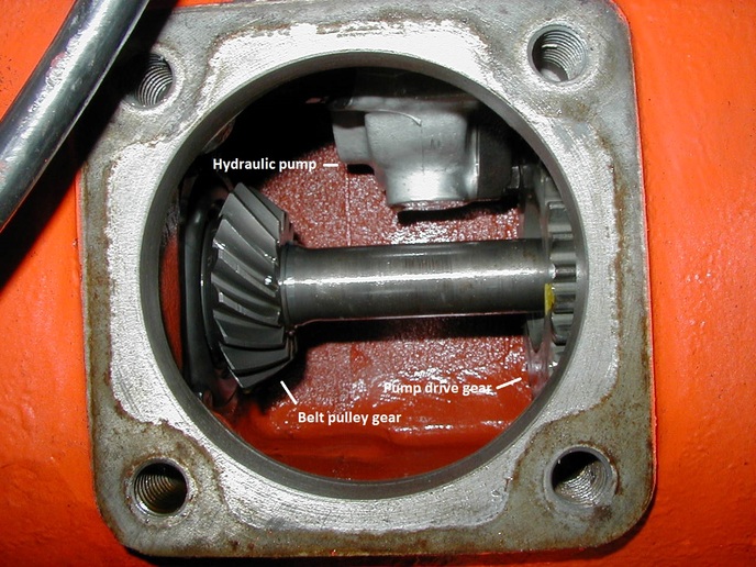
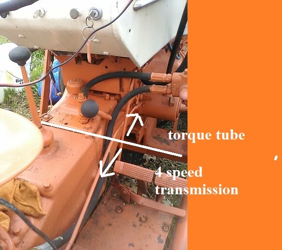
The transition piece from where the bell housing bolts to the engine block back to where
it bolts to the front of 4 speed transmission is the torque tube. Aside from the drive
shaft, intermediate bearing, and belt pulley gear, the torque tube also houses the
hydraulic pump and on you tractor the triple range gear train. It is also used as the
hydraulic reservoir, approx 3 gal hydraulic oil or may have the SAE 10 motor oil or Type A
ATF pending owner preference. The drain plug is on the torque tube aft bottom immediately
in front of where it bolts to the 4 speed transmission.
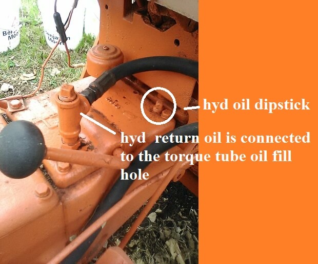
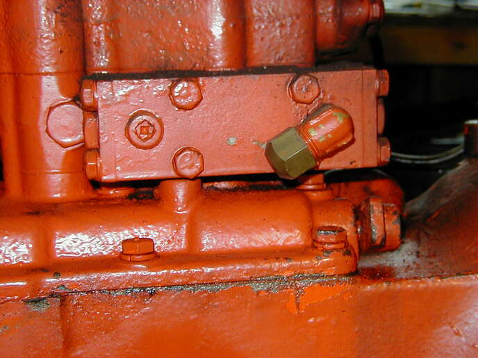
This is 310 utility tractor which is the same here as your 210B, disregard the hand
clutch. Check the dipstick attached to the bottom of that 1/4 pipe plug. If the hydraulic
level is very low that may be the reason the lift cylinders do not work. Lift cylinders
require considerably more oil than the Eagle hitch cylinder. If the torque tube is very
low we need to discuss where it went if not external leak.
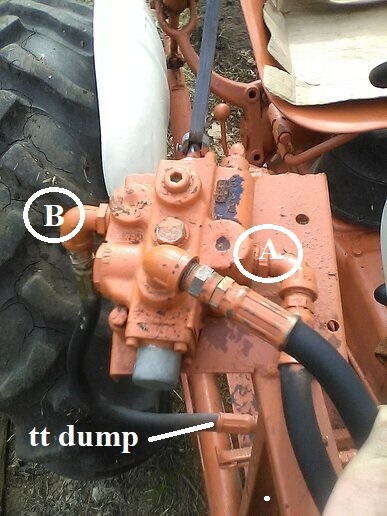
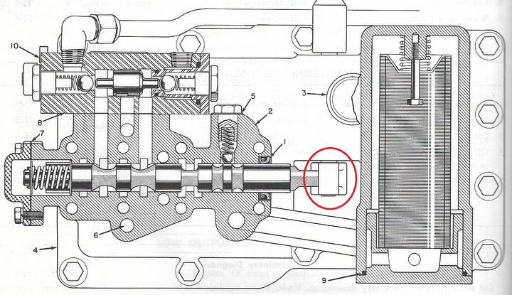
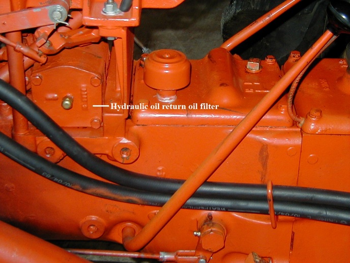
No it is not piped correctly, not saying it will not work as is if it had functioned
before. SA systems are designed to use the same line as supply and return. You system
appears to be dumping the return oil back to the torque tube reservoir as teed into the
fill hole. This defeats the function of the safety interlock and by-passes the return oil
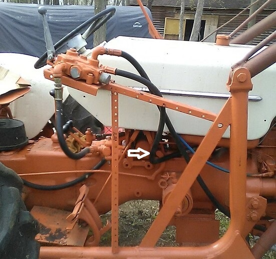
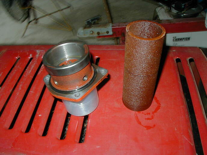
filter. This pic is the oil filter housing on the left side of the tractor under the gas
tank. The original element can be cleaned and reused.


")