Re: Case 210B-L trouble-shooting hydraulic system


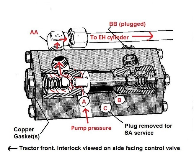
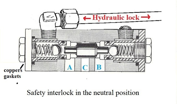
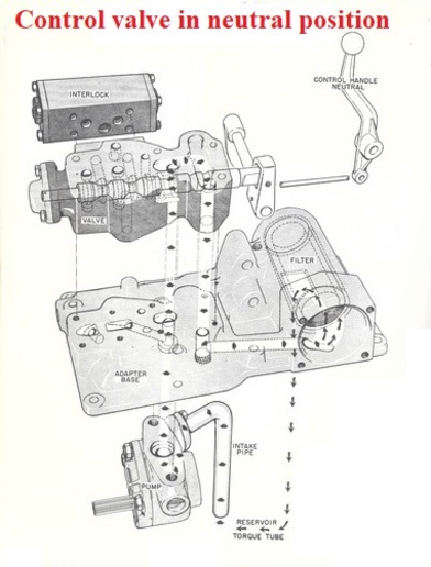
Great cut-away , thx!
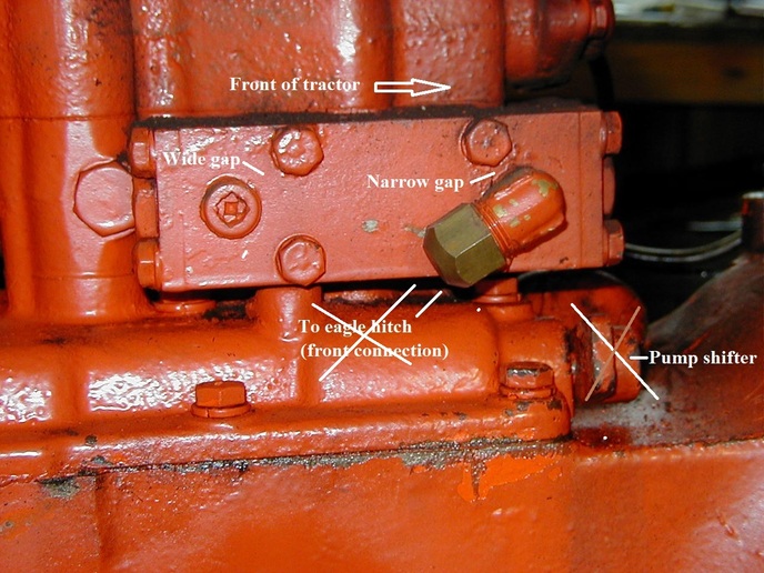
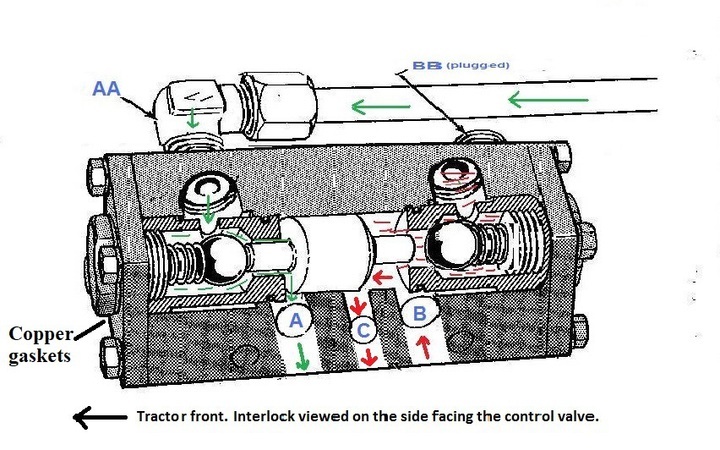
Tricky to get straight on like yours, but here's two pics to make one side view of my PC interlock.

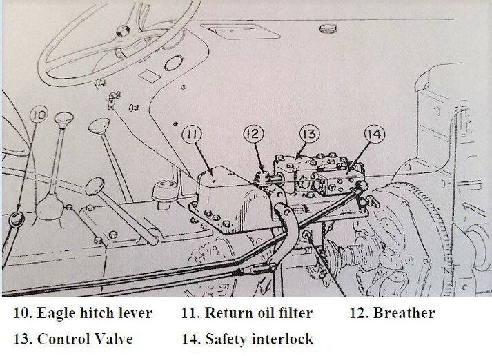
Also, I tried scanning a schematic drawing I did earlier for the existing hydraulic layout on this tractor. Does it make sense? It supports your idea of eliminating the complete LC valve and TT dump while going directly through the SC to either the loader rams or the EH. and just to use the seat lever to operate one or the other. I guess I could live with that as an operational setup to get the tractor functioning. It should sell like that, if the only solution? Perhaps adjustment will be straight forward as I get a chance to tinker? Seems to me there is a couple of "stops" to adjust and some bent rods?
Are you seeing anything better?

mvphoto105230.jpg


mvphoto105231.jpg

mvphoto105237.jpg
 
You can check the interlock mounting. The bolt spacing to fitting gap must be narrower on the front if mounted correctly. It will mount upside down but in that position a port to the control valve will be blind.

cvphoto153669.jpg


This pic may make the EH arrangement clearer.

cvphoto153670.jpg


I have to get on the road. I am not sure I will be able to post tomorrow or Thursday.
 
This is how a SA interlock functions:
EH lever in raise position pump pressure via control valve enters port A unseats ball check and continues to SA system to raise loader or EH..
cvphoto153800.jpg


EH lever back to neutral position, pump pressure via control valve circulates within control valve back to sump via filter. Ball check is seated trapping oil between the ball and SA system, hydraulic lock. The hydraulic lock keeps the SA cylinders in lock position so the loader or EH load does not drop on someone and get you sued if you defeat this safety feature.
cvphoto153801.jpg


cvphoto153802.jpg


EH lever to lowering position. Pump pressure to port B. Plunger unseats ball check, partially uncovers port C to provide a recirc path for pump so it doesn't deadhead in relief. Hyd lock is released on SA system, loader or EH drops by gravity, oil returns to sump via port A, control valve, and filter.
cvphoto153803.jpg


This is why you should have oil supply and return the same path in and out of the interlock. I would run a hose between the interlock and the inlet of the selector valve. Branch out from there with a hose to the EH piston and a hose to the tee for the loader lift cylinders. Use the EH lever to operate the control valve to provide the functions above. Eliminate the existing loader control valve and the return oil dump at the TT cover. Give it a try, you have everything you need there now. Post a one line drawing with components so we can review. You seem to have some doubt about the existing selector valve, you can buy one from a hyd supply or on-line.
 
Thank you for the diagram and explanation confirming the function of the interlock. This is very useful information I will share with the owner, and by which I am confident we can now proceed to re-plumb the loader properly.
FYI: I was able to confirm that a big part of my original confusion/trouble was also due to improper adjustment of the EH linkage (now fixed). Everything seems to work pleasingly well with oil levels stabilized according to the dipstick marks in the torque tube as well as the transmission/rear drive. I believe this was due to previous operators misunderstanding the system, as was I.

As planned now, restoring the interlock function by eliminating the TT by-pass and add-on loader control valve by routing the oil through the selector should provide a better way to operate this tractors hydraulics (2 separate functions; single lever; 3 positions) - At this point, its still worse than awkward to comfortably control and re-stroke the loader arms using both the EH and LC levers in sequence. ESPECIALLY without power assist steering

Sadly, my opportunity to actually pull some wrenches in this undertaking has now slipped away with an unexpected move into other commitments, however I should be able to post the outcome with pics and comments as others involved will hopefully share in the not too distant future.
THANKS again Joe.
Stay tuned
 
(quoted from post at 17:12:23 05/05/23) The main thing is get the return oil going through the filter. Those pumps not available just any where.

You can pipe into the filter cap if that's all you want. You still need the interlock to keep the pump from riding the relief valve on the lowering stroke and it's a good idea not to defeat the hydraulic lock safety feature.
mvphoto105360.jpg
 

We sell tractor parts! We have the parts you need to repair your tractor - the right parts. Our low prices and years of research make us your best choice when you need parts. Shop Online Today.

Back
Top