
wiring diagram

Anonymous-0

Well-known Member
I'm trying to get my ammeter to work. When I bought the tractor the guy said it had a round coil on it. When it went bad he wanted to put everything back the way it was supposed to be. He put new points and 6v square coil on it. No fire. I bought it that way. When I started troubleshooting (of course with help from this site) I found the cause was that a copper piece between concave screw and points was not put back. Put it in there and it fired right up. But ammeter doesnt work. I tried a new one thinking it could be the gauge. None of the diagrams I find match up. The diagrams I find for front mount distributors have a 3 wire generator. Mine has one. It also has only two wires going to regulator. The resistor on the firewall is not being used. I have 6v going into the coil. According to what I've read on here I should have a resistor knocking it down to 3v. But if that were the case why is there a resistor in the coil? I cant make out the serial number. It has 8n 189 on the block. The tractor is a 9n with a 8n engine according to the guy I bought it from. Thanks in advance for any help. Thanks to you guys I have already got it running.
 
The easiest part of your problem to solve is the wiring diagram & the ammeter. Search the archives; you will find plenty of wiring diagrams. The ammeter (unless it's the old induction type) has two terminals. Hook them up per the wiring diagram.

You have me confused regarding your statement " But if that were the case why is there a resistor in the coil?" A front coil does not have a resistor. It needs one & if you keep putting 6v in that coil, you will burn it up, along with your points. The resistor is on top of the terminal block. Put it back in the circuit or get a new one if it's not working.

The above pic is where you will find the serial number.
DSC01804.jpg

50 Tips
 
My serial number is ineligible. I thought the pigtail coming out of the coil was itself a resistor. It had 3 wires going to gauge when I bought it. How many ohm's is the resistor on firewall? Thanks
 
uncfan........here is a picture of the "infamous ballast resistor" that is MANDATORY to be used with the squarecan frontmount ignition coil. It is mounted underneath the ammeter on the backside of dash panel.

Uh? resistance varies from about 0.4-ohm when cold to about 1.7-ohm when hot, normally about 1.2-1.4ohms when running. That is why it is a ballast resistor. Ford's ignition trick for weak 1939 6-volt battery in the before days of DieHards.

2N's have a 1-wire 3rd-brush genny with a 2-terminal roundcan cut-out on the sheetmetal column under the battery tray. You ARE the voltage regulator by manually adjusting the 3rd-brush to about 3-5amps charge on the ammeter. Simple, eh? .......Dell, yer self-appointed sparkie-meister
wm_A8NN12250A.jpg
 
(quoted from post at 07:23:25 02/16/09) I'm trying to get my ammeter to work. When I bought the tractor the guy said it had a round coil on it. When it went bad he wanted to put everything back the way it was supposed to be. He put new points and 6v square coil on it. No fire. I bought it that way. When I started troubleshooting (of course with help from this site) I found the cause was that a copper piece between concave screw and points was not put back. Put it in there and it fired right up. But ammeter doesnt work. I tried a new one thinking it could be the gauge. None of the diagrams I find match up. The diagrams I find for front mount distributors have a 3 wire generator. Mine has one. It also has only two wires going to regulator. The resistor on the firewall is not being used. I have 6v going into the coil. According to what I've read on here I should have a resistor knocking it down to 3v. But if that were the case why is there a resistor in the coil? I cant make out the serial number. It has 8n 189 on the block. The tractor is a 9n with a 8n engine according to the guy I bought it from. Thanks in advance for any help. Thanks to you guys I have already got it running.
quote][b:fda3ac9f21][i:fda3ac9f21]

uncfan;
The way I read this, is that you will NOT find a specific Wiring diagram for the wiring you have, BECAUSE, your charging system is a "single wire Generator", with an 8N regulator.
IE....9N genny with 8N regulator.......CAN work that way, but has to be wired right to get the charging sys. to work right.
We need to see how it is wired, and exactly what gen. is being used.
POST pictures of the Genny, and regulator.
Stock 9N wiring uses a cut-out in the sys., VRS a reg.
Make up your mind as to what charging system you want,(9N or 8N) and I can post a pic. of the wiring for that system.
The regulator that is there, by now has since been ruined, and will prob. need to be replaced or changed to a cut-out. That is prob. the reason your brand new Ammeter does NOT work.
I have a 44 2N, with an 8N charging system, and also have a diagram for that too.
Post the pix. and someone then can help you!!!!!

Gary :roll: [/i:fda3ac9f21][/b:fda3ac9f21][/quote]
 
[b:5e779a7198][i:5e779a7198]

9N/2N stock wiring:
9N_AND_2N_lt_mod-1.jpg


9N/2N with 8N charging system:
9N2Nwiringw-8Nearlygen_lt_mod.jpg


Gary :) [/i:5e779a7198][/b:5e779a7198]
 
If your engine is a replacement short block or an industrial engine, it may not have a serial number. But, chances are it does & you can't read it. Try cleaning the area w/ paint remover & steel wool; don't use sandpaper or any other abrasive because the numbers were hand stamped. Then, use a flashlight to get a a better look. The third wire on the gauge is probably a light. Dell's resistance info is the same as mine; we read the same manuals!
50 Tips
 
(quoted from post at 09:23:25 02/16/09) I'm trying to get my ammeter to work. When I bought the tractor the guy said it had a round coil on it. When it went bad he wanted to put everything back the way it was supposed to be. He put new points and 6v square coil on it. No fire. I bought it that way. When I started troubleshooting (of course with help from this site) I found the cause was that a copper piece between concave screw and points was not put back. Put it in there and it fired right up. But ammeter doesnt work. I tried a new one thinking it could be the gauge. None of the diagrams I find match up. The diagrams I find for front mount distributors have a 3 wire generator. Mine has one. It also has only two wires going to regulator. The resistor on the firewall is not being used. I have 6v going into the coil. According to what I've read on here I should have a resistor knocking it down to 3v. But if that were the case why is there a resistor in the coil? I cant make out the serial number. It has 8n 189 on the block. The tractor is a 9n with a 8n engine according to the guy I bought it from. Thanks in advance for any help. Thanks to you guys I have already got it running.

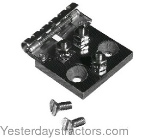
Does your "regulator" look like this (red sq can is a regulator) or like this (round can is a cut-out)?
Dsc_0404_sml.jpg

starterswitch_9N11450B_cutout.jpg
 
(quoted from post at 14:56:52 02/16/09) Square can
Probably wired to utilize the cut out function of the VR and simply does not use the voltage regulation function therein. BATT and ARM (GEN) terminals used and FLD (field) terminal is not connected.
 
(quoted from post at 11:03:25 02/17/09) some pics
a1433.jpg

I see your photos. I assume you are still trying to get ammeter to function?
Does ammeter ever read either chg or discharge(lights on, etc.)?
Have you put a voltmeter on battery to see if voltage is higher running than at rest? These are things to do to determine if ammeter is at fault or if it is reading exactly as it should, as in there is no drain to read or there is no generator output to read.
Now, if those indications are that gen is outputting & a drain shows on ammeter under load, then ammeter still shows zero, we need to examine ammeter wiring.
In your photos, it 'looks like' there might be two wires on left ammeter post in picture(?)....whether 1 or 2, where does other end of the wire(s) connect. Same for right post.....where does other end connect?
At regulator: picture confirms no connection to FIELD terminal (top). For your situation that is as expected & fine. Bottom wire is BATT terminal........where is other end connected?
Middle terminal is ARM....verify that it is connected to generator at other end?
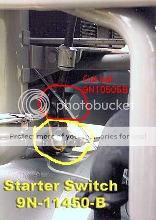
On the starter switch: battery cable side of switch would normally have only one smaller wire connected to that post, in addition to battery cable..........looks like I see two smaller wires..........where is the other end of each connected?

And here, you thought you were going to get answers! And only got a boat load of questions! When we see your answers, maybe we can respond with something in the form of intelligent answers.
 
Here is how it is wired at this time. Looks like I need a resistor between ign sw and coil? Is that what Im missing as far as the 6v going to coil problem? The amp gauge doesnt fluctuate at all. Not when cranking or with lights turned on.Thanks guys!
a1436.jpg
 
(quoted from post at 15:41:14 02/17/09) Here is how it is wired at this time. Looks like I need a resistor between ign sw and coil? Is that what Im missing as far as the 6v going to coil problem? The amp gauge doesnt fluctuate at all. Not when cranking or with lights turned on.Thanks guys!
a1436.jpg

OK. Yes on ign sw to coil resistor. The lighting power in your diagram is NOT passing thru ammeter, thus no meter deflection. Same statement applies for ign current...not passing thru ammeter.
The ONLY current that would pass thru your ammeter would be generator charging current.....if it existed, which it apparently does not.
While running, at speed, temporarily short (jumper) the two lower terminals on the regulator & see if ammeter then shows charge current.
Meanwhile, I'll mark up your diagram, so that if you want to make it more "normal" & read all currents, chg/dischg, then you can alter wiring accordingly.
 
(quoted from post at 16:16:10 02/17/09) I used my digital meter and it said 6.2v at bat. and 8.2 while running and 7.7 with lights on
Are you measuring directly on the battery terminals?

uncfan_elect_prob.jpg
 
(quoted from post at 17:49:22 02/17/09) Yes

Those voltage numbers would indicate that gen/reg charging is functioning.
Throws suspicion back on ammeter. You might try the changes I marked up, just to see if lights might make it show a discharge, but it doesn't seem too likely.
The charge current (green) must be passing thru ammeter or ammeter mounting bracket (if insulating washers are not correct). And if that were the case, I would think the bracket would be shorted to the dash, unless there is a lot of paint insulating bracket from dash.
uncfan_elect_prob-1.jpg
 
I have both terminals on ammeter insulated from bracket. Should one of those be grounded? Im gunna make the changes you suggested tonight.
 
(quoted from post at 18:33:12 02/17/09) I have both terminals on ammeter insulated from bracket. Should one of those be grounded? Im gunna make the changes you suggested tonight.

No, no, no........both ammeter terminals are at battery voltage. Ground one and something will BURN!
 
(quoted from post at 18:46:43 02/17/09) Where should I get resistor?
You can get the 12250 standard resistor from this YT site, nnalert, and several parts places such as NAPA, O'Reilly's, Davis Tractor, etc. Prices vary.
 
I wired everyting like you suggested. When cranking the meter doesnt change. When running it may move a hair if any at all. When I cut the lights on it show -10. I shorted A and. B on the VR and it sparked but showed no change on the meter.
 
(quoted from post at 01:20:41 02/18/09) I wired everyting like you suggested. When cranking the meter doesnt change. When running it may move a hair if any at all. When I cut the lights on it show -10. I shorted A and. B on the VR and it sparked but showed no change on the meter.
4.2 is a bit high, but may be ok. The 12250 resistor is temperature dependent & increases resistance as it gets heated by current, so as to provide more to coil at starting & then taper off as engine runs a minute or two.

neg 10 amps with lights on sounds good.

Would expect to see meter fluctuate during cranking, (ign sw on) showing on/off of coil current, as points open & close. Will of course not show starter motor current (to large to route thru meter).

Would have expected to see + charging current when engine at speed, based on the voltages you reported earlier. Sparking at reg B_A terminal short would indicate cut out contacts must have been open, otherwise B_A would have already been shorted via the closed cut out contacts. Were you at ~ 1/3 to 1/2 throttle?
Also, there is the HIGH/LOW adjustment screw on the rear frame of generator that allows you to increase/decrease generator current. Might try adjusting.

One other test is done with engine off, ign off. Short B_A on reg & you should see ammeter jump far negative as you are trying to dump battery current backwards into a stalled generator. As a matter of fact, if you do this with the fan belt removed from the generator, then the gen will act like an electric motor and spin. Called a "motoring test" of generator & if one will 'motor', it will generally "charge'.
 
Yesterday's Tractor Forums

We sell tractor parts! We have the parts you need to repair your tractor - the right parts. Our low prices and years of research make us your best choice when you need parts. Shop Online Today.

Back
Top