
| Submitted Article |
by Bill Dakin
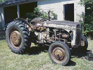 Prior to the start of restoration in late August 1998 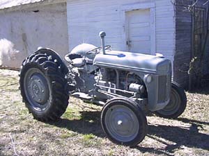 Restoration complete in February 1999 |
Perseverance is not an overused term in describing the extent a restorer will go through in hopes of bringing back a rusting piece of history. Persistence was taught to me at an early age while helping my grandfather go about the chores on the farm. Although we did not tear into any of the tractors for complete repairs, he did put me to work on them plowing wheat stubble, running a disc harrow through the pecan orchard, and driving a grain truck to the elevator. Perhaps all of these fun chores (fun to a city kid) caused me to respect the effort involved in farm and ranching. More than this, the experience permanently recorded the memory of my grandfather that continues today through IHC and Ford antique tractor restoration.
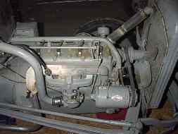
The 1941 9N described in this engine overhaul chronicle developed a few performance problems in late 1998. Indications pointed to the ignition, compression, and moderately low oil pressure which all contributed to a machine that was not efficient and was not fun to operate or maintain. Now the 9N is a joy to drive through the pecan orchard, cut grass, haul pruned branches, or rest at tractor shows. I'm certain my grandfather would be proud today.
Part One: Tearing Down the Engine
Disconnect and remove the battery. Do not set the battery on a concrete floor or near an area that will freeze. For some reason the concrete floor causes degredation of the battery, at least that's what I've read, but it sounds like an old wives tale to me. Apparently this applied to batteries without the cases of today. Remove the hood. |

Drain the gas from the tank through the fuel line. It takes a while but there is no chance of spill. This was done when the garage door was open. Do not open any containers of flammable liquids in an enclosed space and where open flames could be present. |
Disconnect the air cleaner and muffler clamp. Start keeping all the parts in ziplock bags and mark them with a pen. This manifold had a rusted out spot beside the #4 exhaust port that could not be filled enough not to leak. I kept the old one and bought a new manifold for around $68. |
Remove the generator. |
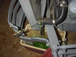
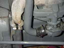
Drain the radiator and coolant from the petcock to the right of the oil filter canister. Remove the bottom hose. Drain the crankcase oil. |
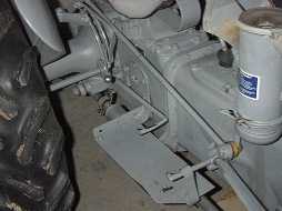
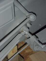
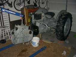
Place a floor jack under the transmission, raise the tractor just enough to remove the weight on the front wheels. Wood blocks then support the housing. Remove the foot rests and running boards. You can also replace the hydraulic pump inspection cover gaskets now if they appear to be leaking. |
Remove the steering arm rods. |
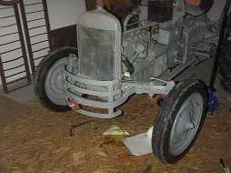
Remove the top radiator hose and pull away the axle assembly with one person holding each radius rod. The assembly is not heavy but akward as the wheels will want to turn in opposite directions, often to the center. Two people can hold one hand on the radius rod and the other hand on the wheel to keep it pointing forward. The radiator must be from an 8N which is pressurized. I'll replace it with the correct radiator if I ever find one. |

Axle assembly rolled away. |
Begin removing the remaining engine accessories... |

Remove the distributor. No need to worry about what position the camshaft is in, when it is reinstalled, the distributor tang will align properly to the cam shaft. |

Remove the large hex and withdraw the oil pressure regulator plunger and spring. The plunger has a flat spot on it which is normal. Buy a new spring before reassembly. The oil pressure was from 50 psi cold to 12 psi hot at working rpm, and now is 43 psi cold to 35-38 psi hot at working rpm. I'm sure now the governor and camshaft gear is receiving more oil. An old spring would not provide the proper oil pressure. |

Governor removed. |

Remove the spark plug wire tube and disconnect the coil wire. Lay the tube and wires back away from the engine. If they are in good shape, there should be no need to remove the wires from the tube. Remove the starter (opposite side). |
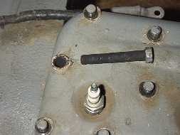
Remove the manifold and carburator. Remove the cylinder head. Depending how you want to lift the engine with a hoist, you may want to leave the cylinder head on prior to engine removal. You can attach the hoist chain and bracket to a manifold stud on one side and a oil canister cap screw to the other side. On reassembly, I used a ring with threaded studs that was attached to the cylinder head center. You can see from this image the cylinder head bolt threads are badly damaged. The threads in the block were damaged also which required drilling and installation of a threaded insert. |
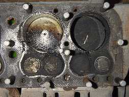
Cylinder #1 and #2 (right to left). Notice heavy carbon and oil escaping by the rings of #2. The blue smoke was apparent every so often, but not enough to foul the plug. |

The cylinder head was thoroughly coated with carbon and oil on #2 (1,2,3,4 right to left). |
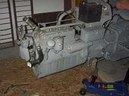
With the cylinder head set back in place, the engine is removed. I decided to disassemble the engine on blocks rather than an engine stand because I didn't want to rent the stand twice or keep it for weeks while the machine work was being done. Pull the engine horizontal away from the transmission to keep from binding on the transmission input shaft. |

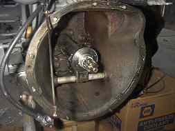
The transmission bell housing, clutch release bearing, and input shaft. Eventually this transmission will be replaced with one from a 2N that has an auxilary Hupp high/low. |

The clutch is removed while still attached to the engine hoist. |

Clutch disk and pressure plate removed. The clutch disk was replaced because of some oil contamination. |

The flywheel can be removed now or when the oil pan is removed to gain better access with a rubber mallet. |

The ring gear around the flywheel was extremely worn but still turned when the starter was engaged. It must be replaced when in this condition. |

The oil pan is removed. At once, remove the oil pump and pick up tube assembly to prevent damage if bumped. Now the flywheel can be tapped off with a mallet or block of wood. A friend should hold the flywheel while it is be tapped to prevent it from falling. It weighs between 35 and 45 pounds. The main bearing caps can be removed now. The caps must be reinstalled later on in the same position in which they were removed. They can be held in place by nails on a small piece of 1x4 and labeled front/middle/rear. |

A check of the oil pan shows some sludge, but a frequent oil change will keep it to a minimum. |
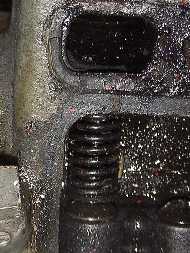
Remove the two valve covers and inspect the valves and chamber. The #4 exhaust valve train and chamber is heavly coated with sludge and carbon. Remove the valve train with a valve spring compressor, pry the assembly down, then remove the retaining ring. This process is by far the most aggravating step in the engine overhaul process. Years of sludge and moisture make the valve train very stubborn to removal. Penetrating oil and persistance usually release them. The machine shop can do it for you, but there is no fun in that. |

The crankshaft pully, timing gear cover, and governor bracket are removed. |

The oil pump and pickup tube. The oil pump overhaul should be done or sent with the other parts to the machine shop for renewing. Often the tube will be loose where connected to the body. This MUST be resecured to prevent air from being sucked into the pump and loss of prime. |

The block will be stripped of all components for the chemical cleaning bath. Some machine shops have an oven to bake out the sludge, but in this project, the shop will use the chemical bath. The cylinder head studs shown will be replaced with grade 8 cylinder head bolts. This will allow the head to be pulled in the future without removing the hood and gas tank. |
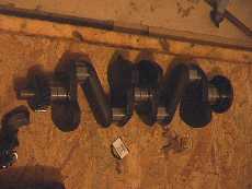
Crankshaft is removed and inspected. The machine shop will check the journals for wear and condition. Grinding is usually necessary to remove scoring and to provide for new babbit bearings with a clearance of 0.001" to 0.0015". |
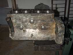
The bare engine block can be lifted into place on the engine stand. The block has been cleaned and new welch plugs installed. These plugs do not function as safety freeze plugs. They are instead were cast as openings to allow the foundry to remove casting sand from deep inside the block. Never allow the block to freeze, if so, you are assured to have a horizontal crack between the two smaller welch plugs. Thin wall sleeves were removed and replaced by the machine shop. |

The block is rotated upside down in preparation to install the bearings and crankshaft, camshaft, and piston/connecting rods. Despite a good chemical cleaning, particles of sludge mud clods came out of the block openings. I used compressed air to completely remove all traces of mud clods. They can be seen on the floor. |

The cylinder head was slightly warped as almost all N series heads are to some degree. This image shows the end result of milling 0.0012". |

The old thin wall sleeves have been removed and replaced with new thin wall sleeves. This image is of cylinder #4 and new exhaust valve. A thread insert was needed as the block threads would not hold the 65-70 ft/lbs torque. |

The new push rods with adjustable tappets were then installed followed by the camshaft. No assembly lube is used until the block and push rods have been drilled to provide an anchor for tappet adjustment. The push rods were then removed and cleaned of all filings. Here, the push rods have been lubed and camshaft installed. It is amazing to me that Ford did not design the block for use with camshaft bearings. And sure enough for this 59 year old tractor, the camshaft did not have any noticeable play within the block. |

Each new valve train is shown installed. |

Close-up showing the adjustable tappets which are rotating when the proper clearances are maintained. Holes of 1/8" diameter have been drilled through the block and push rods to assist in setting the proper valve gap (lash). An ice pick is inserted through the block and push rod to secure it from turning when setting the gap. |

Rear main crankshaft rope seals have been shaped to fit within the housing. Note the use of RTV to provide a complete seal. A very small amount of seal material was removed from each end, but the seal ends must extend above the housing to enable a tight joint between the top and bottom rope seals. RTV was used between the two joints just prior to pan installation. |
|
The bare engine block can be lifted into place on the engine stand. The block has been cleaned and new welch plugs installed. These plugs do not function as safety freeze plugs. They are instead were cast as openings to allow the foundry to remove casting sand from deep inside the block. Never allow the block to freeze, if so, you are assured to have a horizontal crack between the two smaller welch plugs. Thin wall sleeves were removed and replaced by the machine shop. |
The block is rotated upside down in preparation to install the bearings and crankshaft, camshaft, and piston/connecting rods. Despite a good chemical cleaning, particles of sludge mud clods came out of the block openings. I used compressed air to completely remove all traces of mud clods. They can be seen on the floor. |

The crankshaft was turned to give a 0.001" to 0.0015 bearing/journal clearance. Plastigauge revealed the mains between 0.001" and 0.002" were within limits. Here engine assembly lube coats the bearing surface. The lube will quickly blend with the crankcase oil once the engine is run for a few moments. Just long enough for the surfaces to be protected until the oil pump forces crankcase oil throughout the system. |

Bearing and crankshaft rope seal in place. Engine oil coats the rope seal. |

The oil slinger must be installed on the crankshaft in exactly the same orientation it was removed. |

Crankshaft has been placed on the main bearings covered with engine assembly lube. The crankshaft and camshaft MUST be correctly meshed in the right place, or else. Align the "0" and "I", I can't remember which is on which gear. |

The oil pump and front bearing shell combo unit is placed over the front main bearing. Fill the oil pump with assembly lube for priming. |

Installation of the bearing caps and castleated nuts is made with mechanics wire to provide some measure of safety to prevent an unpleasant catastrophe. |

The valve chamber covers are installed with RTV and gaskets in place. |

Here the piston/rings/connecting rod assembly is fed into the bore and tapped into place by using a wood hammer handle and ring compressor. The connecting rod studs within the bore will emerge near the crankshaft. They must not touch crankshaft journal. A small arrow on top of the piston should point to the radiator. |

Oil coats the bore and rings for initial engine run until the oil pump begins to circulate crankcase oil. New valve seats have been installed to provide the greatest possible compression and long valve life. |

The governor support bracket is attached. |

The crankshaft pulley is partially inserted on the crankshaft, but not so far the oil pan cannot clear the pulley when it is installed. The pulley is then pressed on completely after engine assembly. |

A fresh milling of the flywheel is made for superior clutch contact. The input shaft bearing has been installed, and a new ring gear is spot welded in three places. They have been known to spin around the flywheel, and when that happens, you get to split the tractor in two again. |
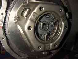
The transmission bell housing. Here a new clutch release bearing has been installed on the input shaft. Check out the two retaining springs for condition, or replace them all together. I've seen these fail and cause aggravation. If significant gear oil is present within the bell housing, the oil seals should be replaced. |
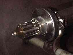
Close up of the clutch release bearing and lube on the input shaft. Movement must be free of binding or hang up. |
The flywheel and clutch assembly have been installed. Alignment of the clutch plate on the input shaft must be made with an alignment tool. |

With the engine assembly complete, the cylinder head and gasket are set in place. A multi-threaded ring is inserted in the block for lifting by the engine hoist. |

The engine is hoisted in to position for sliding on to input shaft and bell housing. Only when then engine is perfectly aligned with the input shaft will the mating surfaces of the engine and bell housing close without binding. A floor jack was used to lift the rear section of the engine. As you can see the rear half is a little low. Two persons will help...one to coax the engine on, and the other to ease the floor jack along. |

Many of the components have been reassembled and painted...axle, steering and radius rods, governor control rod and brackets. At this point, the tractor is back on her feet, and the support blocks removed. |

Radiator, hoses, and generator belt are connected. All new gaskets are used. |

My previous paint job on the hood had a few runs and orange peel. I sanded this down with 300 grit wet sand paper and repainted with NAPA Martin Senour acrylic enamel #6019 and hardener. |

Everything is on except the distributor, wiring, and hood. |

Completed in about 6 weeks of working on weekends and evenings. This included time waiting for back ordered thin wall cylinder sleeves and machine shop work. This photo was taken in front of our house in Plano, Texas. It was something else to see a Ford tractor from 1941 sitting next to Ford Expeditions and mini-vans in our neighborhood. We transported her home to the farm the following week. |
We sell tractor parts! We have the parts you need to repair your tractor - the right parts. Our low prices and years of research make us your best choice when you need parts. Shop Online Today.
Copyright © 1997-2025 Yesterday's Tractor Co.
All Rights Reserved. Reproduction of any part of this website, including design and content, without written permission is strictly prohibited. Trade Marks and Trade Names contained and used in this Website are those of others, and are used in this Website in a descriptive sense to refer to the products of others. Use of this Web site constitutes acceptance of our User Agreement and Privacy Policy TRADEMARK DISCLAIMER: Tradenames and Trademarks referred to within Yesterday's Tractor Co. products and within the Yesterday's Tractor Co. websites are the property of their respective trademark holders. None of these trademark holders are affiliated with Yesterday's Tractor Co., our products, or our website nor are we sponsored by them. John Deere and its logos are the registered trademarks of the John Deere Corporation. Agco, Agco Allis, White, Massey Ferguson and their logos are the registered trademarks of AGCO Corporation. Case, Case-IH, Farmall, International Harvester, New Holland and their logos are registered trademarks of CNH Global N.V.
Yesterday's Tractors - Antique Tractor Headquarters
Website Accessibility Policy