14T- Why can't it bale around turns?

tgrist

Member
I see other Balers continuing to operate while turning online.
I am trying to bale enough to feed a few rescue horses, I cut and bale on small properties 3 acres or less. what used to be a what used to be a hay field is now a subdivision. The landowners allow me to make use of the grass they grow on their properties instead of paying someone to brush hog. Pretty good deal for both of us. This makes for many short runs with many turns.
So, why do I hear a lot of banging and clanging while making turns. I understand that this would put stress on the U-joints. is there a modification that would make baleing around terms possible?
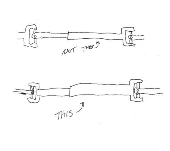
-A thought that I had was to weld the support between the front and back half of the driveshaft in a vertical position and level with the tractor. The Junction between the front and back driveshaft would still be able to Swivel right and left, and the front portion could be replaced with a sliding/extending drive pto shaft.
or is something else causing the banging and clanging on turns?
another piece of information is that it very occasionally (actually the only time it breaks a shear pin) breaks and shear pin when the PTO is shifted into neutral.
 
Make you windrows such that you can start and stop the baler and not make sharp turns. Kick the PTO off and then turn and kick it back on as you start a new windrow. I know bit of a pain but works in tight places
 
It should slide back and forth so you can turn . Is your drawbar on the tractor set to the right length ? Are the ujoints wore out? I had a new holland 283 that the drive line and ujoints were wore out and I couldnt turn at all with the pto running . My international baler I can turn pretty sharp with the pto running
 
Few things to check. Is your drawbar long enough? I think it should be 16" from the center of the hole to the end of the pto shaft. I could be wrong. Are your joints phased correctly? Is there a center support on a 14T? If so, is it set so the shaft is in a straight line, not too high or low at the center support?

I also wonder if a 14T supposed to use an equal angle hitch. If it is, and you don't have it, you'll never get rid of it.

There's no reason you shouldn't be able to do it.
 
14 inches from end of PTO shaft to the center of the drawbar hole for 540 rpm PTO speed. 16 inches is for 1000 rpm PTOs.

Do you have the operator's manual? It gives some set up dimensions for the PTO shaft and adjusting it to the tractor. If you don't have a manual go to https://techpubs.deere.com/ . Choose Equipment Publications and search 14T. The download of the Operator's Manual is a free download.
 

tgrist
I agree drawbar length from end of tractor pto to center in hole of DB should be 14''for 540 rpm pto operation. JD sq balers pto shafts seem to rattle less turning to right than left.

Are telescoping pto u-joints in phase(time) similar to photo below.


One option would be adding an equal angle hitch similar to later model pto operated equipment. This EA hitch addition could be accomplished utilizing 2''b thick x 4'' wide x 12'' long piece of metal a Cat ll bolt-on draft pin & Cat ll weld on ball/socket

mvphoto77618.png
 
It could be the PTO alignment, it could be phasing of the two front u-joints, or it could be worn u-joints. Check them all.

Rake the windrows in a different pattern so that you can turn wide on empty headlands rather than have to turn sharp on heavy windrows.
 
Im not so familiar with green balers.

Typically a baler has a longer shaft and might be slightly off center so the pivot points arent always correct for making the best turns.my NH will turn shorter to the right than to the left.

Constant velocity joints, as you find on new equipment will handle bending much better than the regular cross joint. They are expensive tho. A regular pto cross shaft has to speed up and slow down to make angles, and that is what you are doing to it when you turn short. As the length is odd one end is not making the same angle as the other end, so your shaft has to be spinning at three different speeds as you corner sharp - I know thats difficult to visualize but it is whats happening.. It doesnt bother on a gentle curve, but the tighter you go the bigger deal this is.

So are you lined up properly. Is the shaft and the crossed geared well. Pto height right. All of this helps.

Then shut the pto off on sharp corners. Need to rake the hay so you can make the corners with no hay. Yup, difficult but it can be done.

Paul
 
I have a slightly different set up then that. I have the collar around the drive shaft with the two ears that stick out.
 

cvphoto93373.jpg


cvphoto93374.jpg

I think it's lined up correctly but it still seems off by a tooth. and is my end drive shaft wrong too?
 
I agree with rrlund, that whole drive line is out of phase. That would shake even when you are going straight. Turn everything *90. Mark.
 

If shaft in photo below is square similar to what I think it is I would disassemble one yoke from the square shaft & reassemble it in phase(time) & return the new shiny shaft.

mvphoto77676.png
 

mvphoto77680.jpg


I got it in phase. the drive shaft is rectangular and a U joint yoke was Square. I fit the square hole into the rectangular Peg. instead of drilling I welded it together.quite poorly I might add. this was cobbled together by the previous owner.

if you look closely you can see that the sliding drive shaft is not perfectly aligned and is off by one tooth.
 

Rear 2 u-joints not being exactly in phase shouldn't create driveline vibration because when tongue is in "field position" the driveshaft is virtually in a straight line. While front shaft has to operate in turns at angles.
Due to you putting frt shaft in phase the driveline should vibrate less in turns.

If vibration is still too excessive while making turns then manufacture/install an equal angle hitch I previously referred to.
 
"One option would be adding an equal angle hitch similar to later model pto operated equipment. This EA hitch addition could be accomplished utilizing 2''b thick x 4'' wide x 12'' long piece of metal a Cat ll bolt-on draft pin & Cat ll weld on ball/socket"
I use a Massey Ferguson 65 to pull this baler, it has a swinging hitch (it is currently set to on the swing very little right and left). does that accomplish the same thing?
 
(quoted from post at 08:32:13 06/30/21) piece of metal a Cat ll bolt-on draft pin & Cat ll weld on ball/socket"
I use a Massey Ferguson 65 to pull this baler, it has a swinging hitch (it is currently set to on the swing very little right and left). does that accomplish the same thing?
/quote]

NO not even hardly! Equal angle hitch cause pivot point to be 1/2 way between tractor & baler when set at correct dimensions then the 2 opposing u-joints on that telescoping shaft will be at the same angles therefore eliminating the speed variation with the telescoping shaft therefore lessening the vibration.
 
No you have more to do. The pedestal (front bearing on tongue) would have to be stationary, like on later balers. Also the drive
line from the pedestal to the tractor has to telescope, like on the later balers. Then you could construct parts to make it equal
angle.

The u-joints on your tractor end are out of phase. Someone over the years has replaced parts and welded together wrong. That is
the best you can do without a lot of $$$$
 
(quoted from post at 18:19:48 06/30/21) No you have more to do. The pedestal (front bearing on tongue) would have to be stationary, like on later balers. Also the drive
line from the pedestal to the tractor has to telescope, like on the later balers. Then you could construct parts to make it equal
angle.

The u-joints on your tractor end are out of phase. Someone over the years has replaced parts and welded together wrong. That is
the best you can do without a lot of $$$$

Thanks for pointing the need to change brg pedestal & need for telescoping tractor end of baler pto in order to accommodate a conversion to an equal angle hitch.


Be sure that the mount for the center bearing is free to swivel as in the diagram that Tx Jim posted. Also as young fella posted rake so that the windrows end instead of making sharp turns.
 
(quoted from post at 08:35:38 07/02/21)

Be sure that the mount for the center bearing is free to swivel as in the diagram that Tx Jim posted. Also as young fella posted rake so that the windrows end instead of making sharp turns.

Carrier brg mount I 1st posted is different than the photo of mount I previously posted. Photo below is type tgrist's baler utilizes.

mvphoto77782.png
 
To explain (opening the baler up) for those who may not know, it means putting it into 'field position' versus 'transport position' of the hitch.

I had to think about that a bit as I've never heard that phrase to explain hitch orientation.
 
(quoted from post at 11:51:00 07/02/21) To explain (opening the baler up) for those who may not know, it means putting it into 'field position' versus 'transport position' of the hitch.

I had to think about that a bit as I've never heard that phrase to explain hitch orientation.
thank you for the explanation I actually did not know what that meant. And yes I have opened up the baler before starting to bale.

I tried out the modifications today, the baler seems much happier. The noise and fear of complete destruction is considerably reduced while going around reasonable diameter turns.
I measured the distance on the tractor from the end of the PTO to the hole in the drawbar is 16" currently. I can't remember if there's another hole in the drawbar to make it closer to 14 inches as recommended. I can look at that and upload pictures tomorrow.
1) I also seem to have an intermittent problem with the bill hanging on to the knot. Then if I catch it in time I can cut the string and tie the bale back together by hand
2) in my original post I posed a thought of welding the centerstand solid while still allowing it to swivel. I happen to have a different style center stand shown in the pic below. My thought was to put them on welded or bolted solid with a telescoping PTO shaft in front that. Now would that make me able to bale even tighter turns?
mvphoto77845.jpg
 
(quoted from post at 04:29:50 07/04/21)
(quoted from post at 19:59:34 07/03/21) your pto u joints are not in time

tgrist's U-joints look to be in phase(time) to my old eyes.

mvphoto77882.png
see what he thinks hes seeing. I think the OP is AOK, I think the picture is just low quality and the poster in question is seeing what looks like a 15-20 degree offset in the shaft. Only way it could be like that is if something is twisted up. Heres a good video illustrating why you need to have everything in line and proper. Granted its about automotive driveshafts but same theory applies.

https://youtu.be/Idk3BVDVHq4
 

We sell tractor parts! We have the parts you need to repair your tractor - the right parts. Our low prices and years of research make us your best choice when you need parts. Shop Online Today.

Back
Top