
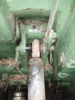
Regarding your top link pin at the tractor end - if I can remember, I'll take a picture of mine today. The pin for my 620 was on it when I bought it. I made the pin for my 630 and it is my favorite. I don't think that a drawbar hitch pin would work good at that location.Ok. A cat I top link pin does fit in all of the holes, sort of. Our pin might be too long though, because we can't insert a pin on the right side due to, well what ever that thing is, and on the left the transmission housing bulges out slightly so there's a bit of an angle. The bottom two will work just fine but if we want the top one for no draft sensitivity we'll need to figure out something else, hopefully just a shorter pin will work. The first pin we tried has a rather wide diameter collar around the head of it and wouldn't go in any of the holes. We did have a much narrower one here that goes into the bottom two just fine but the top two, while the holes are big enough, the angle of the pin cannot be straight so while it goes through the left hole it can't line up with the right hole. Any idea if a Pin for Jd620 specifically is designed to be able to use the top two holes and not be interfeared with by the transmission housing? I suppose a pin that has to be, well, pinned, on both ends instead of just the one, so it doesn't have a head, might work too.
Anyway thanks all. next priority is the poor running. I have a recommendation here to try moving the spark plugs to make sure the problem doesn't follow them, I will try that. Just for fun, if it'll let me I'm going to attach a short audio recording of the engine idling on just the right hand cylinder. I had the throttle blade tied down against the idle speed screw as the manual we have says to do so the governor couldn't compensate and make it so I couldn't hear the sweet spot. As a result, upon starting the engine rpm came up very slowly since the governor couldn't open. I was adjusting the right hand cylinder, turned it in until it went to quit and then turned it back out until it was the fastest.
I recorded that with my Galaxy s21 in my fanny pack, it Since that was on my belly it was almost touching the engine at about where the valve cover is, so it's loud and you can hear every little click from the push rods and whatnot. I shall try to make an actual video at some point.
You are using an out of date browser. It may not display this or other websites correctly.
You should upgrade or use an alternative browser.
You should upgrade or use an alternative browser.
- Thread starter valiant8086
- Start date
valiant8086
Member
Thanks, that's sure to be helpful. If not asking too much can you put how long it is?Regarding your top link pin at the tractor end - if I can remember, I'll take a picture of mine today. The pin for my 620 was on it when I bought it. I made the pin for my 630 and it is my favorite. I don't think that a drawbar hitch pin would work good at that location.
Here's a couple of pictures. I think that the green one is a Deere part. The unpainted one is homemade & I like it better. Measurements are on the next post.Thanks, that's sure to be helpful. If not asking too much can you put how long it is?
Attachments
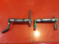
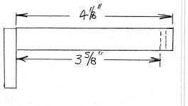
Here's the measurements. The pin is 3/4" and the little handle is whatever will fit the four grooves on the left side of the tractor top link hitch - probably 3/8".Here's a couple of pictures. I think that the green one is a Deere part. The unpainted one is homemade & I like it better. Measurements are on the next post.
Attachments
Try agnHere's the measurements. The pin is 3/4" and the little handle is whatever will fit the four grooves on the left side of the tractor top link hitch - probably 3/8".
You probably already know that you can click on the pictures to make them larger.Here's the measurements. The pin is 3/4" and the little handle is whatever will fit the four grooves on the left side of the tractor top link hitch - probably 3/8".
Attachments

valiant8086
Member
Hi.To add to Tx Jim’s reply- I have a 520 that the clutch was either engaged or not. No way to make an easy start. We removed the pulley assembly and the bearing was shot. A new bearing, toggles and dogs (since it was all apart) and all is great again. Good luck.
Ok so I got the cover off, removed the 3 bolts, pulled off the outer part, it had a pad that came off with it, and 3 springs. There's another disk, then a double sided disk and now I'm down to just nothing I can pull out. I have a big bolt in the middle of a cog. Do we need a bearing puller to go further? My brother is available and has one that he says should be big enough, just checking if I'm not as far as I need to go yet. By the way, not an expert, but all of the disks seem to be in good shape. The surface we're left with after removing all disks is a little rusty. Can feel a slight roughness on them, but they're not pitted, grooved cracked etc. They almost look like they might be brand new and just sat for a long time. I don't know what the thickness is supposed to be, but none of these are super thin. The double sided one is rusty on both sides, not a lot. Dad thinks that's the problem and we could just run it a bunch and it would clear up. With the disks out the clutch handle lever thing moves easily, the bolts move in and out easily by hand and you can pull on one and move the lever forward and it'll pull it in. Obviously that's been working since we can actually engage it ok. Any chance we don't need to go further?
Also the tac doesn't work. It just has one cable going from it to the top of the governer. I took the gauge out and took the inner part of the cable out and plugged it into the back of the gauge, gently tightened a drill onto the other end and ran it. The needle twitches but it won't do anything more than that. This gauge says John Deere on it, but it has a 1000 rpm and a 540 rpm listed for the PTO, is that normal? If this is original gauge maybe I can somehow get it fixed.
buickanddeere
Well-known Member
Odds are the distributer advance mechanism is stuck .Ok two spark plugs. Auto Zone didn't have the ones to match, but they cross referenced and got NGK, $11 for the pair. Gapped to .035. I feel like the service manual says to gap to .030, but the ignition kit says to gap them by .003 wider, or something along that line. Does anybody know the values off-hand?
It runs fabulously, but it's stopping the starter cold every time. The only way to start it is to hold the starter switch when it stops so that it spools up again and then it'll have enough rpm to start next time around. We turned the distributor as far counterclockwise as it'll go without starting to run poorly. We tried revving it up to near max and setting the timing by ear there, but then it wouldn't do low idle, it just shut down completely and we had to hunt the distributor to get it started again. I want to believe the auto advance for rpm is working simply because of how loud and sharp it gets when it's at high speed idles. I don't know how to test it.
As a reminder, this is electronic ignition, eign 18 from external_link, and it has their recommended 55k volts coil and their recommended graphite plug wires. Right now, it's running as smooth as you could ask. It puffs more quietly to itself when idling and gets super loud and sharp at high idle. It doesn't smoke and it's so consistent in firing it sounds like it's the diesel version for all that. It takes throttle from slow idle 375 rpm (tac doesn't work yet) to max (guessing pretty close to 1000) and reaches that in only 5 or 6 loud pops. The only concern is the starter being stopped. If I lean on the starter with the ignition switch off it turns it over just fine. With ignition on, it always stops the starter almost as soon as I press the switch, and I'll never get it started if I'm not smart enough to figure out to hold it to push through that and get it spun up for the full 700 degrees of rotation or what ever so it can power through the next time around.
Free it up and set timing with a light . Before the engine kickback smashes the starter nose .
valiant8086
Member
thanks will try and find out how. I hadn't gone there yet since it gets quiet and retarded sounding, to my relatively inexperienced ears, when it's idling but louder and sharp snaps when revved up. Is the plug gap close enough? .035. I think the manual calls for .030, we increased to .035 for the Pertronix Ignitor That might be slightly too much, no idea how sensitive this should be or whether that can also contribute to the timing challenge.Odds are the distributer advance mechanism is stuck .
Free it up and set timing with a light . Before the engine kickback smashes the starter nose .
My goals at the moment are this issue and the jerky clutch. Haven't done anything to it since my last post, admit to a little waiting around for some hand-holding. Got a feeling I'll learn more if I just turn that big bolt out that's staring at me from the middle of the pulley, but is it by chance threaded backwards or is this a normal bolt? I didn't try yet, I just wonder because the clutch turns clockwise and I feel like I often see spinny things with screw fasceners holding them on threaded backwards in these scenarios.
Fixingfarmer
Member
Yes you can get a new top link. You might want to think about finding a used one at a junkyard that was used on a lot of tractors and it will give you the opportunity to go see what else a place like that has. I’m betting 50 to 75 dollars will get you a good used original one although you might have to work it loose a bit. Just last week I walked over a stack of like 40 lower 3pt arms to get to a shed where all the upper rock shaft lift arms were kept. Find the right guy and he will have more of those than he knows what to do with.Thanks for your reply and the pic, but can't make out the tractor end well enough. When I google top link with cast hinge I believe I'm getting the same 250 and up top links like I get when I put into the steiner website, or on yesterdaystractor.com tractorpartsasap.com etc, that I have a Jd620 and then find the top link. They have an end that goes on the tractor, (a lot of dollars), a center link body (a lot of dollars), and a hook end (yet more dollars), or a complete kit for somewhere never less than $250. People here were saying that I can indeed get a top link from the local farm store and not have to pay that premium. My goal is to not spend $250 to by a dang top link, is that a possibility?
Sorry if it seems like I'm overthinking this. We don't know anything about John Deere so we have to learn as we go. Until we learn, we don't understand where we're missing the obvious things. We just know what we want to accomplish but not quite how to do that until we do.
On your spark plugs this is very common. .030 is fine. You will want to go ahead and just buy the set of 4 in a box so they are cheaper like they sell because you will use them if you are using the tractor. I do mine annually on the B and if it was still running good keep the ones I pulled are in a special spot on the window sill during summer mowing. Since I went to the annual spark plug replacement I don’t have trouble anymore unless I flood and I didn’t do that at all last year. You will get used to your starting procedure. But always on a 2 cylinder have spares a 4 or 6 cylinder you can run with an intermittent miss and life is generally ok if a little underpowered. Not so much on these they need to be tip top which forces you to kinda have it running right if you depend on it. The first year I bet I changed spark plugs more than oil. Now both are at the same time for me it’s just once a year. On e85 it has actually been better in that aspect it doesn’t seem to soot up as easy. You also will want good big batteries good cables because each turn of the crank is half as many(or a 3rd) chances to fire. So if it misses it goes all the way around till it has the opportunity again. They aren’t as hard starting as they sound when you think about it that way. The ignitor kit you did is good. That will eliminate one source of trouble. You will like the ease of working on them once you get in the mindset. Also frequent oil changes! Back then it was 100 hour oil change interval because of flooding and gas contamination. Cheapest locally available Diesel engine oil is what I use. They don’t have a lot of oil either you don’t need to do a filter every time. It’s a very big filter same as 4020 with 1/3 of the work to do.
Have fun with it!
Fixingfarmer
Member
A plain pin with 2 snap clips should also work might have to cut the end off the hitch pin and drill a second hole if that’s what you have laying around
valiant8086
Member
Your pictures and measurements are duely appreciated. I printed them out and they're in with the manuals and other paperwork we're collecting. I intend to tackle both the top link pin and the sway blocks at some point before summer. Moving slowly but surely, the list of problems is headed in the right direction. Need to pull the hood off one more time and hook up the fuel sending unit this time.Try agn
You probably already know that you can click on the pictures to make them larger.
Oh that reminds me, right behind the power troll knob, on the pillar supporting the hood and dashboard, inside of it there is a gadget that has two terminals, and one bolt holding it on. The one on the passenger side used to go to the gas gauge, the one on the driver side used to go to the terminal on the ignition that is powered when switch is in the second notch. Originally, a second wire went from the passenger side of it to the coil. This is a resistor is it not? I think it's not working as such. If I run my dmm on voltage reading with one terminal on the passenger side and the other one on positive battery terminal it still reads 12v. I just get a continuity reading if I put dmm on resistance. Now that the Pertronix Ignitor is here I need continual 12v so bypassed potential resistance by placing coil wire directly on ignition switch. That left only the gass gauge being powered by resistor, and my belief is that it's getting straight 12v anyway. I temporarily ran the wire from gas gauge to same terminal on ignition that holds coil wire, and it was functional and giving level readings seemingly accurate and consistent to movement of float. Can I safely run this gauge like that once I have the sending unit wired to it properly? I currently have the gauge disconnected entirely since the sending unit isn't wired to it anyway. If I need the thing I think is a resistor, I'm going to have to buy a new one. It must have been made out of Epoxy since the passenger end of it broke off about an inch from the end while I was trying to turn the terminal screw. Rogjt mpw since it broke anyway and the gas gauge isn't connected this thing is not connected to anything. I would remove it and not replace it unless I learn that there remains a need of one. Going to redo the wiring at some distant point since it's kind of hodge podged the way it is, both before and after we got our hands on it.
valiant8086
Member
If I run my dmm on voltage reading with one terminal on the passenger side and the other one on positive battery terminal it still reads 12v. I just get a continuity reading if I put dmm on resistance.
Sorry, I meant if I have it on resistance and put one terminal on each end of the supposed resistor, and this test was done before I broke it.
Fixingfarmer
Member
I think the gas gauge shouldn’t need a resistance other than what the sender does on the backside that’s how it reads. If you did positive ground ignitor kit and still have same generator same battery cables hooked up everything should be the same. I wonder if what you have there is a breaker and might be popped but a picture should verify.
620 John
Member
The clutch driver bolt that you're talking about is a normal RH thread bolt. Hopefully yours is tight. Very common on any two cylinder to have the bolt slowly over time work loose causing the clutch driver to come loose and wear out the splines on the driver and crankshaft. When you take that bolt out take note of the clutch driver position on the crankshaft. Ideally the clutch driver should be about a 1/4" protruding from the end of the crank. Quite common for them to be 1/8" or less. If it's flush with the crank then you got problems which could explain the jerky clutch. ALSO NOTE THAT THE CLUTCH DRIVER HAS TIMING MARKS THAT LINE UP WITH ANOTHER MARK ON THE CRANKSHAFT. THE DRIVER NEEDS TO BE TIMED TO THE CRANKSHAFT OR YOU'LL HAVE A VIBRATION. If the marks are not visible make your own timing marks.thanks will try and find out how. I hadn't gone there yet since it gets quiet and retarded sounding, to my relatively inexperienced ears, when it's idling but louder and sharp snaps when revved up. Is the plug gap close enough? .035. I think the manual calls for .030, we increased to .035 for the Pertronix Ignitor That might be slightly too much, no idea how sensitive this should be or whether that can also contribute to the timing challenge.
My goals at the moment are this issue and the jerky clutch. Haven't done anything to it since my last post, admit to a little waiting around for some hand-holding. Got a feeling I'll learn more if I just turn that big bolt out that's staring at me from the middle of the pulley, but is it by chance threaded backwards or is this a normal bolt? I didn't try yet, I just wonder because the clutch turns clockwise and I feel like I often see spinny things with screw fasceners holding them on threaded backwards in these scenarios.
I highly recommend getting a service manual if you haven't already. It'll explain how to take the clutch apart. JD didn't make a service manual specifically for the 620 so generally the model 60 service manual is used which is SM2008. Google that number and you'll find quite a few out there. I like the ones from Jensales personally.
valiant8086
Member
The clutch driver bolt that you're talking about is a normal RH thread bolt. Hopefully yours is tight. Very common on any two cylinder to have the bolt slowly over time work loose causing the clutch driver to come loose and wear out the splines on the driver and crankshaft. When you take that bolt out take note of the clutch driver position on the crankshaft. Ideally the clutch driver should be about a 1/4" protruding from the end of the crank. Quite common for them to be 1/8" or less. If it's flush with the crank then you got problems which could explain the jerky clutch. ALSO NOTE THAT THE CLUTCH DRIVER HAS TIMING MARKS THAT LINE UP WITH ANOTHER MARK ON THE CRANKSHAFT. THE DRIVER NEEDS TO BE TIMED TO THE CRANKSHAFT OR YOU'LL HAVE A VIBRATION. If the marks are not visible make your own timing marks.
I highly recommend getting a service manual if you haven't already. It'll explain how to take the clutch apart. JD didn't make a service manual specifically for the 620 so generally the model 60 service manual is used which is SM2008. Google that number and you'll find quite a few out there. I like the ones from Jensales personally.
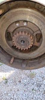
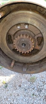
Ok, so ours is completely flush, but our service manual makes it look like it is flush too. The bolt was tight. I couldn't get it out with an 8 inch ratchet bouncing off compression and yanking on it. Had to get the impact out. It got it out set on medium, so about 700 lb.ft.
I'll see if I can't put these two pictures. We're going to get the bearing puller hopefully tomorrow. Belongs to my brother so waiting on him to have a minute. Our manual says to put the big bolt, which it calls a cap screw, back on without the large washer and then use the puller, presumably the puller's center pin thing will push on the bolt head.
Attachments
valiant8086
Member
Can anyone confirm about the disk needing to be protruding past end of shaft? What's the fix if mine is not supposed to be completely flush like that? I think I might have encountered a clutch drive disk that was supposed to be a little extra thick although I don't know right off if that was this part or if it was one of the plate things. Once I get behind this disk I think I might replace all the toggles and dogs if money permits and put it back together hoping that worked even though the drive disk may be worn a bit.Ok, so ours is completely flush, but our service manual makes it look like it is flush too. The bolt was tight. I couldn't get it out with an 8 inch ratchet bouncing off compression and yanking on it. Had to get the impact out. It got it out set on medium, so about 700 lb.ft.
I'll see if I can't put these two pictures. We're going to get the bearing puller hopefully tomorrow. Belongs to my brother so waiting on him to have a minute. Our manual says to put the big bolt, which it calls a cap screw, back on without the large washer and then use the puller, presumably the puller's center pin thing will push on the bolt head.
By the way, the clutch plates, or pads, what ever they're called, all have a little bit of like a sticky gunk on them. In theory that would be increasing friction and reduce ability to get an easy start. Can we do something to get that off without damaging the disks which otherwise, to the best that we can tell are in excellent condition?
Might have to send you pictures of those also.
valiant8086
Member
Yeah, any ideas on cleaning these clutch pads? Thought about trying in the sink with dawn dishwashing liquid.
flying belgian
Well-known Member
Its been many years but Pa would take the cover off the 60 pulley and squirt some used motor oil in there. That got rid the grabby clutch.Welcome to this forum
Concerning grabby clutch I'll advise to remove clutch pully which requires a drive disk to be pulled off splined end of crankshaft. Then put grease on toggles & dogs plus packing bearing located in pully housing with grease
Similar threads
We sell tractor parts! We have the parts you need to repair your tractor - the right parts. Our low prices and years of research make us your best choice when you need parts. Shop Online Today.
Copyright © 1997-2024 Yesterday's Tractor Co.
All Rights Reserved. Reproduction of any part of this website, including design and content, without written permission is strictly prohibited. Trade Marks and Trade Names contained and used in this Website are those of others, and are used in this Website in a descriptive sense to refer to the products of others. Use of this Web site constitutes acceptance of our User Agreement and Privacy Policy TRADEMARK DISCLAIMER: Tradenames and Trademarks referred to within Yesterday's Tractor Co. products and within the Yesterday's Tractor Co. websites are the property of their respective trademark holders. None of these trademark holders are affiliated with Yesterday's Tractor Co., our products, or our website nor are we sponsored by them. John Deere and its logos are the registered trademarks of the John Deere Corporation. Agco, Agco Allis, White, Massey Ferguson and their logos are the registered trademarks of AGCO Corporation. Case, Case-IH, Farmall, International Harvester, New Holland and their logos are registered trademarks of CNH Global N.V.
Yesterday's Tractors - Antique Tractor Headquarters
Website Accessibility Policy