
Doug Kieta
Member
I am adding a 1-wire alternator conversion to my 1949 Super A. Does anyone have a wiring diagram that shows the connections to the back of the 3 position switch (low charge/high charge/lights). Appreciate any help offered.
A three position Light switch has no connection to the charging system at all. The 4 position switches did have control of earlier generators, but the three positions on your switch are Off Dim Bright turning from CCW to CW. There is no connection to the new alternator other than a 10 gauge wire to the amp gauge from the alternator. Change the polarity of the amp gauge so it reads correctly. change the polarity of the ignition coil (negative to the distributor) and put in 12v bulbs. JimI am adding a 1-wire alternator conversion to my 1949 Super A. Does anyone have a wiring diagram that shows the connections to the back of the 3 position switch (low charge/high charge/lights). Appreciate any help offered.
Bob M’s diagrams has all references, 1 wire, 3 wire, gens. You really shouldn’t run a 1 wire to the amp gauge, should be run to the positive battery cable stud on push button or solenoid. Then change out amp gauge for a voltmeter, wire appropriately.There is a diagram in this post by jvermast it is for a 3 wire alternator but all you have to do ignore the two wires that go to the 1 & 2 terminals on the battery.
YT post with wiring diagram Just pretend they are not even there. The wire coming off the ammeter to the left of the diagram should go to the terminal on the light switch that powers the fuse. What kind of a coil are you using? If you use the original 6 volt coil you will need an approximately 1.5 ohm resistor to place in the power lead to the coil. I am going to have to find a 1 wire alternator diagram for Farmalls. I had a link to one before the site software switch over but it no longer works.
RedVa, for a tinkering around Super A wiring through the ammeter is fine. He will just be starting it occasionally and maybe have a few lights on it. Now if it is a cab tractor, with a heater blower, A/C clutch and running whatever monitors or other electronic equipment I would agree sent all those amps direct to the battery cable and the feed point they are all being drawn. Monitor it with a volt meter as you suggest. JMHOBob M’s diagrams has all references, 1 wire, 3 wire, gens. You really shouldn’t run a 1 wire to the amp gauge, should be run to the positive battery cable stud on push button or solenoid. Then change out amp gauge for a voltmeter, wire appropriately.
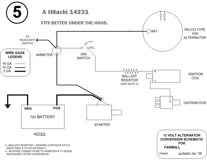
With respect, 1 and 2 terminals on the alternator instead of battery in the first sentence (I think you meant). The foundation of assessing a charging system by looking at an on board meter has gone the way of idiot lights. Either an amp meter, or a volt meter can be used but both depend on two conditions, the first is looking at them every few minutes of operation, the second is having a clue as to what one is looking at. If I recommend wiring a "one wire" alternator. I also think a fuse link or high amp fuse holder of 5% greater than alternator amp rating be in that single wire in the circuit to limit fire hazard and melted components. JimThere is a diagram in this post by jvermast it is for a 3 wire alternator but all you have to do ignore the two wires that go to the 1 & 2 terminals on the battery.
YT post with wiring diagram Just pretend they are not even there. The wire coming off the ammeter to the left of the diagram should go to the terminal on the light switch that powers the fuse. What kind of a coil are you using? If you use the original 6 volt coil you will need an approximately 1.5 ohm resistor to place in the power lead to the coil. I am going to have to find a 1 wire alternator diagram for Farmalls. I had a link to one before the site software switch over but it no longer works.
Yes, disregard circuits to 1 & 2 terminals on the alternator. Thanks for the correction. Now you can just follow the diagram Barnyard posted.With respect, 1 and 2 terminals on the alternator instead of battery in the first sentence (I think you meant). The foundation of assessing a charging system by looking at an on board meter has gone the way of idiot lights. Either an amp meter, or a volt meter can be used but both depend on two conditions, the first is looking at them every few minutes of operation, the second is having a clue as to what one is looking at. If I recommend wiring a "one wire" alternator. I also think a fuse link or high amp fuse holder of 5% greater than alternator amp rating be in that single wire in the circuit to limit fire hazard and melted components. Jim
it’ll work fine, I’ve done it once or twice that way, I prefer the voltmeter. Simpler imho and keeps that charge wire out of boxes and dashes. Janicholson’s point about a fuseable link would be best option and should be done if running it to the amp meterRedVa, for a tinkering around Super A wiring through the ammeter is fine. He will just be starting it occasionally and maybe have a few lights on it. Now if it is a cab tractor, with a heater blower, A/C clutch and running whatever monitors or other electronic equipment I would agree sent all those amps direct to the battery cable and the feed point they are all being drawn. Monitor it with a volt meter as you suggest. JMHO
I would suppose not, so long as you disregarded the connection from the amp meter to a disturbitor.All these responses assume the tractor has an ignition coil. My SA is outfitted with a magneto. Does this change any of your opinions on how to wire the alternator so it keeps the battery charged?
Thanks for the help.
Nope! Wire per the diagram above, only omit the wiring/switch to the ignition coil.All these responses assume the tractor has an ignition coil. My SA is outfitted with a magneto. Does this change any of your opinions on how to wire the alternator so it keeps the battery charged?
Thanks for the help.
Didn’t assume anything, doesn’t really make any difference. Just makes it simpler to wireAll these responses assume the tractor has an ignition coil. My SA is outfitted with a magneto. Does this change any of your opinions on how to wire the alternator so it keeps the battery charged?
Thanks for the help.
Nothing, you should only have one wire from switch to the mag, it’s a grounding switch, nothing moreSo then what happens to the wire coming from the ignition switch to the coil. Where does it connect?
Should say with a grain of salt that I’m basing what I said on it was still original wiringNothing, you should only have one wire from switch to the mag, it’s a grounding switch, nothing more
We sell tractor parts! We have the parts you need to repair your tractor - the right parts. Our low prices and years of research make us your best choice when you need parts. Shop Online Today.
Copyright © 1997-2024 Yesterday's Tractor Co.
All Rights Reserved. Reproduction of any part of this website, including design and content, without written permission is strictly prohibited. Trade Marks and Trade Names contained and used in this Website are those of others, and are used in this Website in a descriptive sense to refer to the products of others. Use of this Web site constitutes acceptance of our User Agreement and Privacy Policy TRADEMARK DISCLAIMER: Tradenames and Trademarks referred to within Yesterday's Tractor Co. products and within the Yesterday's Tractor Co. websites are the property of their respective trademark holders. None of these trademark holders are affiliated with Yesterday's Tractor Co., our products, or our website nor are we sponsored by them. John Deere and its logos are the registered trademarks of the John Deere Corporation. Agco, Agco Allis, White, Massey Ferguson and their logos are the registered trademarks of AGCO Corporation. Case, Case-IH, Farmall, International Harvester, New Holland and their logos are registered trademarks of CNH Global N.V.
Yesterday's Tractors - Antique Tractor Headquarters
Website Accessibility Policy