
Bought my 850 a year ago and have been restoring it. Got it running great but noticed it wasn't charging the battery. After a little diagnosis I found that someone had wired it for 6v negative ground system. Wiring was old with cracked insulation so I bought a restoration quality wiring harness and wired it according to factory diagram in the maintenance manual bringing back to a positive ground system. I also bought a new Voltage regulator and generator that was a replacement for the original part number to insure I had the right regulator for it. The new generator is an OHA-10125-A and is suppose to be a replacement for the original part number. I verified all wiring was correct according to the diagram and that I had a good ground at the VR. Polarized the generator before I started it. It started right up, but I noticed the ammeter was pegged at 30 amps. Turned the lights on and it went to 20 amps and stayed there for a while and then went to zero. I assumed the regulator had stopped the charging because the battery was fully charged when I started. Occasionally it would show it charging at 30 amps and then go to around zero. Turned the tractor off after about an hour of operation and noticed that the system was discharging at about 20 amps and lights were off. Checked the VR and it was fried. Replaced the VR with another new one, this time the one that the place I bought the generator from recommended. Stamped on it is "6 Volts Positive Ground B-Circuit" so I assumed I was ok there. Repolarized the generator and started the tractor. Same thing happened and the VR smoked. I have rechecked the wiring and grounds and everything still checks out. Could not find the specs on the generator I bought but it is a 6 volt generator. I suspect it is the generator but want to know for sure before I send it back. Any thoughts on how to diagnose the problem would be greatly appreciated.
You are using an out of date browser. It may not display this or other websites correctly.
You should upgrade or use an alternative browser.
You should upgrade or use an alternative browser.
- Thread starter RHaydu
- Start date
Bern
Well-known Member
- Location
- Mount Vernon, WA
The only way I can think that a generator could fry a regulator is if the field coils have a short to ground
or lower than normal resistance in them. Grab an ohmmeter and check the resistance from the "F" post of the
generator to the frame of the generator (or ground post) with the wires disconnected. According to the
manual, it should read approximately 3 ohms. Anything less than this would likely indicate your problem.
On a related note, your description of the amp gauge when first starting is normal. The amp gauge should be
reading the amount of current being restored to the battery, not what current the generator is putting out.
Once the engine has been running for a while, and the battery is fully charged, it is quite normal to see an
ammeter reading at or near zero.
This probably doesn't apply, but has an RF noise suppression condenser been added at the generator or VR?
On the odd chance someone is done that, it is to be connected to the "A" (Armature terminal) at the generator or the "BATT" terminal at the regulator.
If the condenser is connected to the "F" terminal at the generator or the regulator it will supposedly cuase premature failure of the field relay points in the regulator over time.
We had a early 851 6 volt system, and after the original VR failed, had VR problems. Took the generator to a rebuilder and he said there was circuit changeover during manufacture. He said he matched the VR to the generator and would guarantee the outcome. Tractor was sold shortly after, so I can't provide any more information. Perhaps there is a clue in here.
Bern
Well-known Member
- Location
- Mount Vernon, WA
Sounds like you're on to something. Did you zero your leads before you did the check? If you didn't, and you
have the typical .5 or so ohm lead resistance, that means your actual resistance of the field coils is even
lower than what you reported.
BTW, the actual spec from the Ford repair manual is 3.2 ohms, so if it really is 2.1 ohms, then you're off
by about 30%.
have the typical .5 or so ohm lead resistance, that means your actual resistance of the field coils is even
lower than what you reported.
BTW, the actual spec from the Ford repair manual is 3.2 ohms, so if it really is 2.1 ohms, then you're off
by about 30%.
Tim PloughNman Daley RIP
Well-known Member
Electrical will work on positive or negative ground so that isn't your root cause problem. I suspect it is in the wiring but avoid guessing. If you have the OEM generator I would have rebuilt it rather than buy something "new". Did you motor test it first? Do you still have it? I can rebuild it to OEM specs if so. The OEM generator is a 3-Wire/2-Brush, 20 AMP, Shunt Wound unit. Did you polarize the generator via the VR correctly? The 'B' Circuit is polarized differently than an 'A' circuit and if you do it wrong you will smoke it. Aftermarket generators (and other parts) use their own part numbers so means nothing. Do you have a Clymer/I&T FO-20 Manual? The OEM Ford 600/800 Owner/Operator?s Manual is helpful as well. Here's a page with a quick test method. They are very useful tools. How are the lights wired? Headlights were OEM beginning with the 800 tractors but you can always remove them just to take them out of the equation.
FORD NAA, 600, 800 ELECTRICAL WIRING SYSTEM, OEM 6V/POS GRN:

GENARATOR A & B CIRCUIT POLARIZING VIA VR:

Tim Daley(MI)
FORD NAA, 600, 800 ELECTRICAL WIRING SYSTEM, OEM 6V/POS GRN:
GENARATOR A & B CIRCUIT POLARIZING VIA VR:
Tim Daley(MI)
rvirgil_KS
Well-known Member
Are you primarily interested in function or originality?
If your concern is function and reliability, your problems with generator regulators are one of the primary reasons for considering an internal regulated alternator conversion.
If your concern is function and reliability, your problems with generator regulators are one of the primary reasons for considering an internal regulated alternator conversion.
not to add more mystery... generators need to be current limited as to not melt the solder out of the stator... And therefore the regulator MUST be calibrated for that amperage output of that generator. So a 11 amp gen must have a 11amp vr... A 22 amp gen must have a 22 amp vr.
Then a battery with a bad cell will keep the charging circuit at max and keep the current at max, so a poorly design vr will fry.
So you must match the gen and voltage regulator...
(quoted from post at 13:39:43 01/06/20) armature, commutator
yes... should have said armature... A commutator is a person who gives pardons??
") thanks for the correction. We used to clean the mica grooves between the copper strips lightly, when installing new brushes. Then a front bearing and rear bearing and back in service.. anything more complex required it go to the generator shop.. a few would have the armature worn down to nearly the shaft.
thanks for the correction. We used to clean the mica grooves between the copper strips lightly, when installing new brushes. Then a front bearing and rear bearing and back in service.. anything more complex required it go to the generator shop.. a few would have the armature worn down to nearly the shaft.ot sure, might be able to give pardons :?:(quoted from post at 19:57:38 01/06/20)(quoted from post at 13:39:43 01/06/20) armature, commutator
yes... should have said armature... A commutator is a person who gives pardons??
https://images.search.yahoo.com/yhs...iversal_motor_commutator.jpg&action=click
Bern
Well-known Member
- Location
- Mount Vernon, WA
The commutator is the rear part of the armature, where the brushes ride.
AG State sent me a new Generator after the second VR smoked. Retraced all the wiring, replaced the ammeter just in case, and removed the light circuit just in case. Wiring checked out according to the Ford manual. Put the new generator in and started her up. At about 1100 RPMs she was reading 20 amps solid. Ran it to 1500 RPM and it reads 30 amps. Brought it back down to 1100 and it went back to 20. So from a previous post it should read 20 amps at 1650 RPMs. So I am thinking the pulley on the generator is to small which is causing the generator to put out to much current at normal working RPM and is over driving the VR and eventually letting the smoke out. The pulley on my 850 is 3 inch in diameter (outer). Anyone know what size the pulley should be? Or am I barking up the wrong tree :?:
ot sure on 850, but older N tractors were either 3 or 3.5 inches diameter. However, the current output is limited by the voltage regulator and not the generator.(quoted from post at 17:30:21 01/20/20) AG State sent me a new Generator after the second VR smoked. Retraced all the wiring, replaced the ammeter just in case, and removed the light circuit just in case. Wiring checked out according to the Ford manual. Put the new generator in and started her up. At about 1100 RPMs she was reading 20 amps solid. Ran it to 1500 RPM and it reads 30 amps. Brought it back down to 1100 and it went back to 20. So from a previous post it should read 20 amps at 1650 RPMs. So I am thinking the pulley on the generator is to small which is causing the generator to put out to much current at normal working RPM and is over driving the VR and eventually letting the smoke out. The pulley on my 850 is 3 inch in diameter (outer). Anyone know what size the pulley should be? Or am I barking up the wrong tree :?:
You have said several times that the smoke was let out.....be specific as to which item inside the VR burned to make the smoke....good photos would be nice. Pulley size is almost certain NOT to be your problem.


The bottom picture is the first one that went. Tried to rotate it but it wouldn't let me. Top one is the second one and the only visible damage I could find was the heat marks on the right side. Same side as the first one. The first one was a part match from the ford parts list in the Ford manual. The second one was the one AG State said matched the generator I got from them. The generator is supposed to be a match for the original part number. On both occasions when I shut of the tractor the ammeter went to -20 amps. The current VR I presume is still fine, ammeter reads 0 when I turn the tractor off.

(quoted from post at 21:41:45 01/20/20) I'll look more in the light of day....tooo late tonight.

Added a top view of the first VR
Sean in PA
Well-known Member
Are you sure you are buying the proper voltage regulators? The circuit drawing you posted from the Ford manual shows the three terminals labelled as "A" for armature, "F" for field, and "B" for battery, but your last picture shows the terminals of your VR labelled "PRM", GND", and "BAT". I am not sure what type of VR that is, but I am pretty sure that GND stands for ground, and in the circuit drawing it is the case that is grounded, not the middle terminal.
'm with Sean on the GND terminal....never in all the types of regulators that I have experienced have I ever seen ARM-GND-BATT terminal arrangement. Further more, the cut out side is the burnt side and it looks to have a strange contact arrangement , such as I have not seen i a regulator before either. What, where does this critter come from?(quoted from post at 09:08:20 01/21/20) Are you sure you are buying the proper voltage regulators? The circuit drawing you posted from the Ford manual shows the three terminals labelled as "A" for armature, "F" for field, and "B" for battery, but your last picture shows the terminals of your VR labelled "PRM", GND", and "BAT". I am not sure what type of VR that is, but I am pretty sure that GND stands for ground, and in the circuit drawing it is the case that is grounded, not the middle terminal.
as I said earlier, its the vr's job to control current and keep it safe... and the correct vr is needed to match the generator. I dont know that you have the correct regulator.
Is this a positive ground 6 volt system still? Did someone change it to negative ground and not repolarize the generator correctly?
DId someone put a 12 volt generator on this system?
Does the battery have a shorted cell making it over current?
and do you have the correct vr??? to match the generator???
((I have seen batteries put in backwards and forced into a reverse charge. Its rare but can happen. And causes lots of current when doing so. One was a pos grnd 24 volt system on a fire truck. One 8d was backwards and the other was correct. Battery guy said to leave it as it worked and reversing the battery again would probably warp the cell plates due to the heat. ))
(quoted from post at 10:40:37 01/21/20)'m with Sean on the GND terminal....never in all the types of regulators that I have experienced have I ever seen ARM-GND-BATT terminal arrangement. Further more, the cut out side is the burnt side and it looks to have a strange contact arrangement , such as I have not seen i a regulator before either. What, where does this critter come from?(quoted from post at 09:08:20 01/21/20) Are you sure you are buying the proper voltage regulators? The circuit drawing you posted from the Ford manual shows the three terminals labelled as "A" for armature, "F" for field, and "B" for battery, but your last picture shows the terminals of your VR labelled "PRM", GND", and "BAT". I am not sure what type of VR that is, but I am pretty sure that GND stands for ground, and in the circuit drawing it is the case that is grounded, not the middle terminal.
Jesse, I'm pretty sure the middle terminal is marked "FLD" in "Land of Almost Right" typeface!

hat would certainly make much more sense than GND, but the goofy looking contact arrangement on the cut out stand still looks odd to me....however, in the melted state, it is difficult to be sure what was there before.. It does look as though overcurrent was the cause. I would speculate the the over current was a result of battery feeding current thru VR into generator as opposed to generator output. My thoughts.(quoted from post at 11:55:12 01/21/20)(quoted from post at 10:40:37 01/21/20)'m with Sean on the GND terminal....never in all the types of regulators that I have experienced have I ever seen ARM-GND-BATT terminal arrangement. Further more, the cut out side is the burnt side and it looks to have a strange contact arrangement , such as I have not seen i a regulator before either. What, where does this critter come from?(quoted from post at 09:08:20 01/21/20) Are you sure you are buying the proper voltage regulators? The circuit drawing you posted from the Ford manual shows the three terminals labelled as "A" for armature, "F" for field, and "B" for battery, but your last picture shows the terminals of your VR labelled "PRM", GND", and "BAT". I am not sure what type of VR that is, but I am pretty sure that GND stands for ground, and in the circuit drawing it is the case that is grounded, not the middle terminal.
Jesse, I'm pretty sure the middle terminal is marked "FLD" in "Land of Almost Right" typeface!
I got both the generator and the second and current VR from ALL State AG Parts and was what was recommended for the generator I purchase. The 3 terminals are BAT, FLD, ARM. The tractor is wired exactly as the diagram I posted above from the original Ford manual. The first VR (Really Fried one) was a part number replacement for the original VR and may not of been a match for the generator. The matched VR is not limiting the current as it should (See my above posts).


he current limiting functions only when charging, which is part of the reason that I said the over current was likely to have occurred when engine off & battery feeding back toward generator. Cutout contacts being closed.(quoted from post at 22:22:23 01/21/20)
I got both the generator and the second and current VR from ALL State AG Parts and was what was recommended for the generator I purchase. The 3 terminals are BAT, FLD, ARM. The tractor is wired exactly as the diagram I posted above from the original Ford manual. The first VR (Really Fried one) was a part number replacement for the original VR and may not of been a match for the generator. The matched VR is not limiting the current as it should (See my above posts).
JMOR,
So your thought on the back current casing the VR to fry may be valid, I can't dispute it. It doesn't explain why when I am running at norming operating RPM the ammeter is reading 30 amps, when the max the manual say it should be 20 amps at 1600 RPM. I can get to read 20 amps when I am at 900 RPM. I measure voltages at the battery, VR, and generator to see if that leads me any where. I will also check the battery for a damaged cell. The battery is only 6 months old but I will check it anyway. It may turn out that the VR isn't match for the generator like ALL State AG Parts say it is.
So your thought on the back current casing the VR to fry may be valid, I can't dispute it. It doesn't explain why when I am running at norming operating RPM the ammeter is reading 30 amps, when the max the manual say it should be 20 amps at 1600 RPM. I can get to read 20 amps when I am at 900 RPM. I measure voltages at the battery, VR, and generator to see if that leads me any where. I will also check the battery for a damaged cell. The battery is only 6 months old but I will check it anyway. It may turn out that the VR isn't match for the generator like ALL State AG Parts say it is.
ounds like a plan(quoted from post at 20:15:55 01/22/20) JMOR,
So your thought on the back current casing the VR to fry may be valid, I can't dispute it. It doesn't explain why when I am running at norming operating RPM the ammeter is reading 30 amps, when the max the manual say it should be 20 amps at 1600 RPM. I can get to read 20 amps when I am at 900 RPM. I measure voltages at the battery, VR, and generator to see if that leads me any where. I will also check the battery for a damaged cell. The battery is only 6 months old but I will check it anyway. It may turn out that the VR isn't match for the generator like ALL State AG Parts say it is.
AND>>>>>>> the pos(positive+) terminal of the battery is connected to ground and the negative terminal of the battery is connected to the starter selonoid?? AND... when you put a meter on the battery, and put the black lead on the negative post and the red lead on the positive post, you correctly read 12 volts.. and is it a digital meter? just making sure of the details here.
I have seen twice now, where a battery was put in backwards and actually force to take on a reverse charge and still work... And for a while the current was very very very high till the battery totally went down and then reversed...
The generator may be polarized backwards or wrong... so we need to stop and take a breath here.
n his defense, he did say in very first post, " Polarized the generator before I started it.".(quoted from post at 19:54:33 01/23/20)
AND>>>>>>> the pos(positive+) terminal of the battery is connected to ground and the negative terminal of the battery is connected to the starter selonoid?? AND... when you put a meter on the battery, and put the black lead on the negative post and the red lead on the positive post, you correctly read 12 volts.. and is it a digital meter? just making sure of the details here.
I have seen twice now, where a battery was put in backwards and actually force to take on a reverse charge and still work... And for a while the current was very very very high till the battery totally went down and then reversed...
The generator may be polarized backwards or wrong... so we need to stop and take a breath here.


I have both a digital and a really good analog meter. For the purpose of the picture I used the digital meter so you can read it. So the battery was installed correctly. Analog meter read the same. According to the Ford manual I have, "the generator is polarized by disconnecting the field wire and the battery wire from their terminals at the regulator, and momentarily touching the two together (Engine not running)". That is what I have been doing each time a swap a generator or regulator.
I started her up and set her to idle at 900 rpm. Ammeter read 20 amps, 8.2 V across the bat terminals. Then set the idle at 1100 rpm and the ammeter read 30 amps and measured 8.45 V across the battery terminals. I also checked the ground between ground terminal on the generator and the tractor body and read zero. So did the reading from the VR case to the tractor body and the positive lead to the battery. So I am not sure were to go from here. On the end plate of the generator it is stamped with the ford logo and "OHA-10125-A". Does any one have one of those, if so what VR are you using with it?
f field contacts can not open, then VR can't limit gen output, voltage or current.(quoted from post at 15:22:36 01/24/20) When running at either speed, measure voltage on Field terminal. If same as ARM or BATT, then I would remove power & open VR & verify that field contacts (normally closed) are not stuck/welded closed & therefore not free to open.
So went out and fired her up and she went up to 30 amps so I throttled her back to 900 rpm to get it down to 20 just in case. I measured as you suggested and found that the FLD was not the same as the BATT or ARM so I checked the ammeter and it was reading less then 10 amps so I brought the RPM up to 1500 and it went to 12 amps which is what I would expect to see. Watched it for a bit and it popped up to 30 amps so I back it down and shut it off. I removed the VR cover to check the contacts and they looked fine. So I started it up and it went back to acting normal, around 10 amps. I could see the relay being held open. Turned the tractor off and started up and again it acted normal. Scratched my head at this so I shut off the tractor, put the VR cover back on, and started it back up. Back to 30 amps it went. Touched the cover to see if it was hot and it went back to normal, jiggled it a little and back to 30 it went. Shut it off, removed the cover it was back to normal, about 10 amps. Let it run for while and saw it go to near zero, which I assume means the battery was fully charged. Shut it off, went to the store, came back, cranked it up, still normal! So the cover was interfering with the VRs operation. Must be a bad design because I was having the same issue with the last VR which was the same make and model as the current one. I guess I could leave the cover off, I live in the Desert and humidity is not a problem. Dust would be though. I will try adding the rubber gasket from the other VR tomorrow and see if that fixes it, unless you have a better idea? Thanks again for your help!
nteresting. Make sure the cover is not touching any internals. Grease, color markers, etc.(quoted from post at 21:01:58 01/24/20) So went out and fired her up and she went up to 30 amps so I throttled her back to 900 rpm to get it down to 20 just in case. I measured as you suggested and found that the FLD was not the same as the BATT or ARM so I checked the ammeter and it was reading less then 10 amps so I brought the RPM up to 1500 and it went to 12 amps which is what I would expect to see. Watched it for a bit and it popped up to 30 amps so I back it down and shut it off. I removed the VR cover to check the contacts and they looked fine. So I started it up and it went back to acting normal, around 10 amps. I could see the relay being held open. Turned the tractor off and started up and again it acted normal. Scratched my head at this so I shut off the tractor, put the VR cover back on, and started it back up. Back to 30 amps it went. Touched the cover to see if it was hot and it went back to normal, jiggled it a little and back to 30 it went. Shut it off, removed the cover it was back to normal, about 10 amps. Let it run for while and saw it go to near zero, which I assume means the battery was fully charged. Shut it off, went to the store, came back, cranked it up, still normal! So the cover was interfering with the VRs operation. Must be a bad design because I was having the same issue with the last VR which was the same make and model as the current one. I guess I could leave the cover off, I live in the Desert and humidity is not a problem. Dust would be though. I will try adding the rubber gasket from the other VR tomorrow and see if that fixes it, unless you have a better idea? Thanks again for your help!
nother thought: the magnetic effects of the metal cover could come into play.(quoted from post at 23:15:36 01/24/20)nteresting. Make sure the cover is not touching any internals. Grease, color markers, etc.(quoted from post at 21:01:58 01/24/20) So went out and fired her up and she went up to 30 amps so I throttled her back to 900 rpm to get it down to 20 just in case. I measured as you suggested and found that the FLD was not the same as the BATT or ARM so I checked the ammeter and it was reading less then 10 amps so I brought the RPM up to 1500 and it went to 12 amps which is what I would expect to see. Watched it for a bit and it popped up to 30 amps so I back it down and shut it off. I removed the VR cover to check the contacts and they looked fine. So I started it up and it went back to acting normal, around 10 amps. I could see the relay being held open. Turned the tractor off and started up and again it acted normal. Scratched my head at this so I shut off the tractor, put the VR cover back on, and started it back up. Back to 30 amps it went. Touched the cover to see if it was hot and it went back to normal, jiggled it a little and back to 30 it went. Shut it off, removed the cover it was back to normal, about 10 amps. Let it run for while and saw it go to near zero, which I assume means the battery was fully charged. Shut it off, went to the store, came back, cranked it up, still normal! So the cover was interfering with the VRs operation. Must be a bad design because I was having the same issue with the last VR which was the same make and model as the current one. I guess I could leave the cover off, I live in the Desert and humidity is not a problem. Dust would be though. I will try adding the rubber gasket from the other VR tomorrow and see if that fixes it, unless you have a better idea? Thanks again for your help!
George (VA)
New User
Just saw this after a frustratingly fruitless search on the same topic in many places.
Any joy yet? My 53 NAA is doing the same thing. 6V positive ground. Same regulator. I don?t see any
regulator meltdowns, but have a pegged ammeter. Volts runs from about 7.8 low throttle to nearly 10
revved up. Pull field wire & it stops charging amps to zero. Motors fine. Not thinking it?s the Genny;
either VR or possibly battery? It holds 6.3 and passes a load test, but hydrometer shows borderline. Battery is four
years old, might get a new one anyway. All wiring has been triple checked.
If you?ve solved it, please let us know!
Take the generator, and the VR to the auto electric shop. Tell them it is 6V pos ground. Ask them to set up the VR so it charges properly. They will show you how to connect it. Follow their directions carefully. BATT is easy, but the other two need to be specific depending on type of Gen. They may tell you that the VR is incompatible with the gen type.
I've been through this twice, it's the only way to get it right.
I've been through this twice, it's the only way to get it right.
I haven't solved it yet. I have found that if you run it with the VR cover off, it acts normal. I ran the tractor last weekend for couple hours doing some work around the property still with the VR cover off. I kept an eye on the ammeter and did notice when the VR went into charge mode the ammeter would peak quickly at 30 amps and settle down to 10-12 amps, until the battery was fully charged and then would go to near zero and stay there until the next charge cycle. Put the VR cover back on after the 2 hours and the ammeter went back to 30 amps solid unless I throttled it back to less then 900 rpm were it would stay at 20. So still scratching my head. So I work with a bunch of engineers (EEs and MEs) me being one as well and we had a real geek session discussing the issue this week. I had previously verified that the cover wasn't hitting either of the relays so the group thinks that what I have is a cheap Chinese knock off and if the cover, cover screws, and base don't make solid contact on both sides I am getting currents through the cover creating a magnetic field effecting the regulation circuits. Probably a stretch that this is the issue but I am going to remove the cover paint around the mounting holes and make sure I have good contact. If that doesn't solve, and I don't have high hopes that it will, plan B is to buy another VR from a known manufacture and see if that solves it. I will let you know what happens.
few pieces of plastic, glue, tape and you have a non-magnetic cover, even if only for educational purposes, or a permanent 3D printed cover? Magnetic and temperature are both altered with/without cover.(quoted from post at 11:44:18 02/07/20)
If my plan B doesn't work I will take it down to a shop as you suggested but not sure where that will get me seeing it works like its supposed to with the cover off. I do appreciate the suggestion though, thanks.
heck wife's plastic storage containers. :idea:(quoted from post at 12:42:12 02/07/20)
At least until I solve the problem without using this work around as a permanent solution.
George (VA)
New User
Think I solved it!
And thanks for the tip about pulling the cover. Though it did not work for me, I thought I?d push the arm
down with a screwdriver. Just the shaft being in the magnetic field settled out the ammeter. Which led
me to this thought:
It needed a bit more ferrous mass up top. Used an electrical knockout & ground a slot & drilled some
holes to attach it to arm with safety wire.
Now reads good on amps, a bit low on volts 6.6 and Genny is cool to the touch.
See pix if I posted correctly.
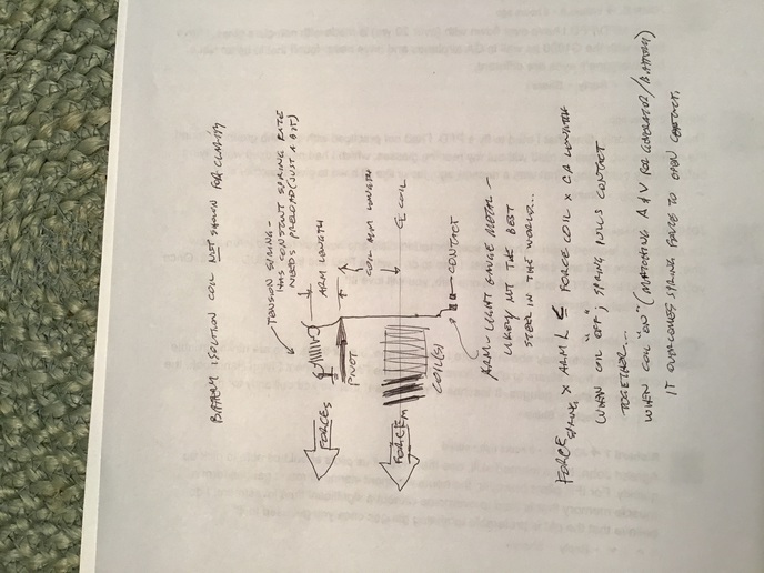
I think the spring on that coil is too stiff. The case is stamped OK but with the long history of post-ers
with this problem, it must be the cheap imported units.
Post back if it fixes yours.
And thanks for the tip about pulling the cover. Though it did not work for me, I thought I?d push the arm
down with a screwdriver. Just the shaft being in the magnetic field settled out the ammeter. Which led
me to this thought:
It needed a bit more ferrous mass up top. Used an electrical knockout & ground a slot & drilled some
holes to attach it to arm with safety wire.
Now reads good on amps, a bit low on volts 6.6 and Genny is cool to the touch.
See pix if I posted correctly.
I think the spring on that coil is too stiff. The case is stamped OK but with the long history of post-ers
with this problem, it must be the cheap imported units.
Post back if it fixes yours.
(quoted from post at 17:59:58 02/08/20) Love the ingenuity! I will give that a try. Did you add knockouts to both the relays or just the one shown in the picture?
R/ Rick
Just for the record, as to how this works, he modified the combination voltage and current regulating unit, the other "unit" is the "cutout relay".
In the combo unit, there is a heavy winding that carries generator output current and a lighter winding that is energized with generator output VOLTAGE both wound on the same core.
(Not that many voltage regulators "back in the day" were made with THREE units, a voltage regulating unit, a current regulating unit, and the cutout relay and BOTH charging current AND voltage could be accurately set "in the field".)
Each winding on his combined unit generates magnetic field that acts on the "armature" to tend to pull the contacts open and limit charging current and voltage.
According to various published info on how these "vibrating contact voltage regulators work, once the battery is charged the contacts typically "make and break" in the area of 60 times a SECOND.
Dunno why you'd want to add MASS to a part that moves like that, charging rate adjustment would typically be made by simply bending the stationary tab the spring hooks to.
It would be interesting to see an accurate reading of the charging voltage at the battery with this "improved" setup.
It would be an AMAZING stroke of luck if the "mod" is producing an acceptable regulated charging voltage while also regulating current to a safe level!
For a "two unit" voltage regulator to accurately regulate both generator output voltage AND limit current to a safe value, both the voltage and current windings have to be wound to exact "specs" and then fine-tuned by selecting a spring and setting it's tension during "live" testing after assembly.
(quoted from post at 00:06:24 02/09/20) Bob, can you recommend at good VR manufacture. Obviously the one that All State AG parts sells that supposedly matches the generator I have is not well made. I have tried 2 of them with the same results. Thanks
Sadly, no.
On the other hand, some of the old stuff I work on uses Delco electrics, and I search ebay and the 'net for "NOS" parts quite often.
Delco was unique in that they "canned" their replacement parts, and if one finds a certain part in an unopened container, it's usually as good as it was when it left the factory.
Not always true for stuff in shelf-worn boxes.
I am - sad that people make up !$#%&! like this and call it a 'fix'. I've been an EE for 45 years, and invariably, I see work like this that will not last for more than a short time.
Bob above gave a very excellent discussion of how the crowbar current regulation operates, along with the voltage regulation with double wound core.
An analog voltage regulator is set for a generic generator voltage when built. One does not always have a 'generic' generator voltage, mostly due to time in the field, carbon brush build up, stator magnetization, and slip/split ring resistance.
So - one more time. The FIX is to take off the gen, and the VR, take them to a old tyme generator repair shop, and they will spin the gen, and set the spring tension, or bend the hooked tab to get it to put out the correct current at the correct voltage for the application. Some tractors had 20 amp units, some had 23, 25, and even 30 amp units. The shop will look at your gen, and run the test, and set the VR to proper spec.
Otherwise, it will: 1. Burn out the new VR. 2. Melt a winding and fry the gen. 3. overcharge and boil the battery(this is where things were headed with the 30 amp charge at high RPM). 4. All of the above.
George (VA)
New User
Wow. Haters or disbelievers, no need to ?cuss?!
The overall point is that quality replacements are difficult to find ( would LOVE to pick up a canned NOS unit!)
My 40 years as an ME & another 7 or so messing with hot rods tells me that this is a force balance
issue with these imported VRs. Bob is entirely correct in how these VRs work, assuming they come from overseas in a correct ?as originally designed? configuration. I stand on my premise (especially after an
inordinate amount of time trying to ?adjust? the spring) that the spring is way too stiff for this application, or the coil doesn?t have the force in this configuration to open the contact
Anyway, no joy in finding a suitable spring.
Adjusting a tension spring with too much stiffness is impossible by tweaking the length. They need a
pretension to work and the working travel is pretty short to begin with. To correctly tweak it, one would
need to change the moment length from the pivot point to the spring coil ride point. Or change out the
spring with less tension/ wire gauge, or more overall wound diameter. Not sure if any old or new shop can adequately set these imported VRs up. Maybe if it were a third brush unit?
What I did was to add ferrous mass to allow the magnet to ?grip? ( for lack of a better term) the contact
arm and pull it against the spring. The steel quality is not likely what was used in the 1950s. Ferrous mass is why the generators and starters weigh more than an empty bean can.
Results? Holding 8-10 amps charge & 7.04 volts consistently with 2-plus hours of bush-hogging.
A coil will not burn out unless the amps are excessive for the wire size or the volts level exceeds the
varnished insulation.
?It ain?t stupid if it works?.
And if I had the money to send every problem out hoping it will come back right, I?d be riding a nice new orange tractor!
f it works for you, I say GOOD FOR YOU!(quoted from post at 17:57:06 02/20/20) Wow. Haters or disbelievers, no need to ?cuss?!
The overall point is that quality replacements are difficult to find ( would LOVE to pick up a canned NOS unit!)
My 40 years as an ME & another 7 or so messing with hot rods tells me that this is a force balance
issue with these imported VRs. Bob is entirely correct in how these VRs work, assuming they come from overseas in a correct ?as originally designed? configuration. I stand on my premise (especially after an
inordinate amount of time trying to ?adjust? the spring) that the spring is way too stiff for this application, or the coil doesn?t have the force in this configuration to open the contact
Anyway, no joy in finding a suitable spring.
Adjusting a tension spring with too much stiffness is impossible by tweaking the length. They need a
pretension to work and the working travel is pretty short to begin with. To correctly tweak it, one would
need to change the moment length from the pivot point to the spring coil ride point. Or change out the
spring with less tension/ wire gauge, or more overall wound diameter. Not sure if any old or new shop can adequately set these imported VRs up. Maybe if it were a third brush unit?
What I did was to add ferrous mass to allow the magnet to ?grip? ( for lack of a better term) the contact
arm and pull it against the spring. The steel quality is not likely what was used in the 1950s. Ferrous mass is why the generators and starters weigh more than an empty bean can.
Results? Holding 8-10 amps charge & 7.04 volts consistently with 2-plus hours of bush-hogging.
A coil will not burn out unless the amps are excessive for the wire size or the volts level exceeds the
varnished insulation.
?It ain?t stupid if it works?.
And if I had the money to send every problem out hoping it will come back right, I?d be riding a nice new orange tractor!
<img src="https://www.yesterdaystractors.com/cvphotos/cvphoto5844.jpg">
(quoted from post at 10:59:51 02/07/20)few pieces of plastic, glue, tape and you have a non-magnetic cover, even if only for educational purposes, or a permanent 3D printed cover? Magnetic and temperature are both altered with/without cover.(quoted from post at 11:44:18 02/07/20)
If my plan B doesn't work I will take it down to a shop as you suggested but not sure where that will get me seeing it works like its supposed to with the cover off. I do appreciate the suggestion though, thanks.
Back in the olden days (50's)... the regulator shop used to say that a vr will charge .5 volts higher with the cover off and putting the metal cover back on would lower it. So they set the vr .5 volts higher to allow for this????
In your case, its either touching,, or the cover is warping the vr base so the tension on the relays is distorted or binding the contacts?????
is there anything that pushes on the cover or vr base?
Is the base loosing its ground with the cover on? Some vr's have a little ground wire between the base and the tractor mount.
you need to keep the water and dust out of it.. so maybe a tupperware container might sacrifice itself??
Similar threads
- Replies
- 8
- Views
- 733
We sell tractor parts! We have the parts you need to repair your tractor - the right parts. Our low prices and years of research make us your best choice when you need parts. Shop Online Today.
Copyright © 1997-2024 Yesterday's Tractor Co.
All Rights Reserved. Reproduction of any part of this website, including design and content, without written permission is strictly prohibited. Trade Marks and Trade Names contained and used in this Website are those of others, and are used in this Website in a descriptive sense to refer to the products of others. Use of this Web site constitutes acceptance of our User Agreement and Privacy Policy TRADEMARK DISCLAIMER: Tradenames and Trademarks referred to within Yesterday's Tractor Co. products and within the Yesterday's Tractor Co. websites are the property of their respective trademark holders. None of these trademark holders are affiliated with Yesterday's Tractor Co., our products, or our website nor are we sponsored by them. John Deere and its logos are the registered trademarks of the John Deere Corporation. Agco, Agco Allis, White, Massey Ferguson and their logos are the registered trademarks of AGCO Corporation. Case, Case-IH, Farmall, International Harvester, New Holland and their logos are registered trademarks of CNH Global N.V.
Yesterday's Tractors - Antique Tractor Headquarters
Website Accessibility Policy